


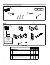


J-Series Installation Instructions
8
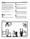
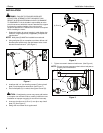
Figure 6
4. Tighten all hardware.
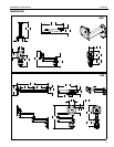
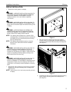
CABLE MANAGEMENT
1. Attach all cables to display.
CAUTION: Ensure that adequate cable slack exists for
movement of display, and that cables will not be pinched by
installation of cable management cover(s) (E) or screws (G).
2. Carefully insert cables in cavity located in lower portion of
mount arm (See Figure 7).
3. Install cover (E) with two 8-32 x 3/8" Phillips screws (G).
(See Figure 7)
Figure 7
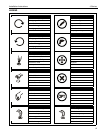
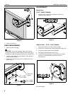
ADJUSTMENTS
Swing Arm
PIVOT / SWING TENSION
1. Slightly loosen or tighten the adjustment screw(s) as
necessary (See Figure 8).
Figure 8
DISPLAY ROLL / PITCH / YAW TENSION:
1. Disconnect all wires and cable from the display.
2. Remove two Lower screws securing display to Centris cup.
3. Loosen two Upper screws securing display.
4. Lift display upward and away from mount.
5. Turn the tension adjustment screw clockwise to increase
tension, or counter-clockwise to decrease tension.
(See Figure 9)
Figure 9
Re-install display.
3
x 2
2
(G) x 2 (JWS)
Cable Path
(typical)
(E) x 1 (JWS)
3
(G) x 4 (JWD)
(E) x 2 (JWD)
1
5