


JWDSK Series Installation Instructions
6
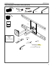
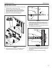
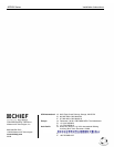
Figure 5
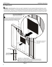
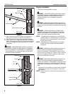
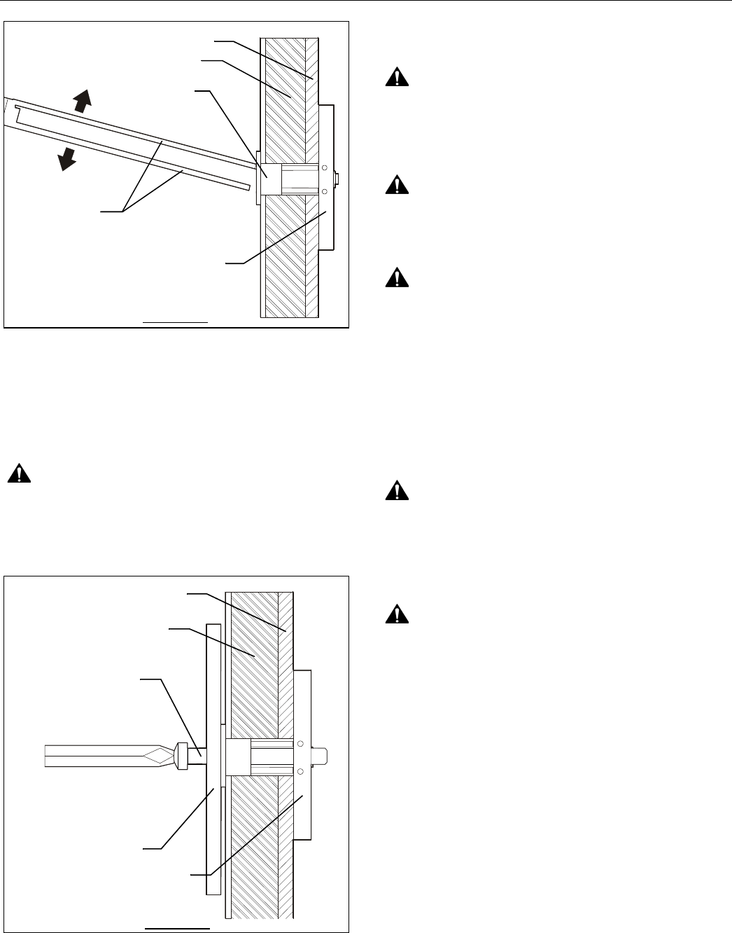
11. Place mount over anchors and align mounting holes in
display mount with holes in anchors. (See Figure 6)
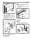
12. Place flat washer (E) onto Phillips pan head screws (D).
13. Insert 1/4-20 x 1-3/4" Phillips pan head screw (D) with flat
washer (E) through mounting hole in display mount and into
anchor (F) and tighten until flush against mount. DO NOT
overtighten!
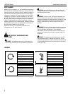
WARNING:
IMPROPER INSTALLATION CAN LEAD TO
EQUIPMENT FALLING CAUSING SERIOUS PERSONAL
INJURY OR DAMAGE TO EQUIPMENT! Overtightening of
mounting hardware can damage the steel studs. DO NOT
overtighten mounting hardware!
Figure 6
Display Installation
1. Determine mounting pattern on display.
WARNING:
IMPROPER INSTALLATION CAN LEAD TO
EQUIPMENT FALLING CAUSING SERIOUS PERSONAL
INJURY AND DAMAGE TO EQUIPMENT! DO NOT
substitute hardware. Use only hardware supplied by
manufacturer!
WARNING:
IMPROPER INSTALLATION CAN LEAD TO
ELECTRIC SHOCK OR DAMAGE TO EQUIPMENT! Screw
length must not exceed the depth of threaded mounting insert
in display.
WARNING:
OVERTIGHTENING OF SCREWS CAN
DAMAGE PARTS AND LEAD TO SERIOUS PERSONAL
INJURY AND DAMAGE TO EQUIPMENT! DO NOT over
tighten screws when installing interface bracket.
NOTE:
If the display being installed has a 100x100 VESA
mounting pattern, no interface bracket is required and
the display can be mounted directly to the mounting
plate as outlined below.
NOTE:
If the display being installed requires an interface
bracket, refer to the interface bracket installation
instructions.
WARNING:
IMPROPER INSTALLATION CAN LEAD TO
DISPLAY FALLING CAUSING SERIOUS PERSONAL
INJURY OR DAMAGE TO EQUIPMENT! Using screws of
improper size may damage your display! Proper screws will
easily and completely thread into display mounting holes.
Ensure that screws are not too long.
WARNING:
IMPROPER INSTALLATION CAN LEAD TO
DISPLAY FALLING CAUSING SERIOUS PERSONAL
INJURY OR DAMAGE TO EQUIPMENT! Inadequate thread
engagement in display may cause display to fall! Back out
screws ONLY as necessary to allow installation of mounting
plate!
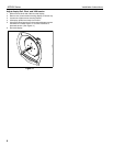
1. Start two M4 x 12mm Phillips pan head screws (included in
hardware kit) into upper mounting holes in display back.
(See Figure 7)
NOTE:
Leave at least 1/8" of each screw protruding out back
of display.
Plastic Straps
Steel Stud
Drywall
Anchor Metal Channel
Plastic Cap
SIDE VIEW
Steel Stud
Drywall
Anchor Metal Channel
Display Mount
SIDE VIEW
(E) x 4
(D) x 4