


Installation Instructions Model: FSR Series
5
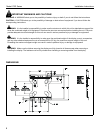
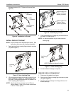
collapsed anchors (20). Tighten until secure (See
Figure 4).
Figure 4: Installation to Drywall
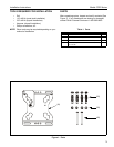
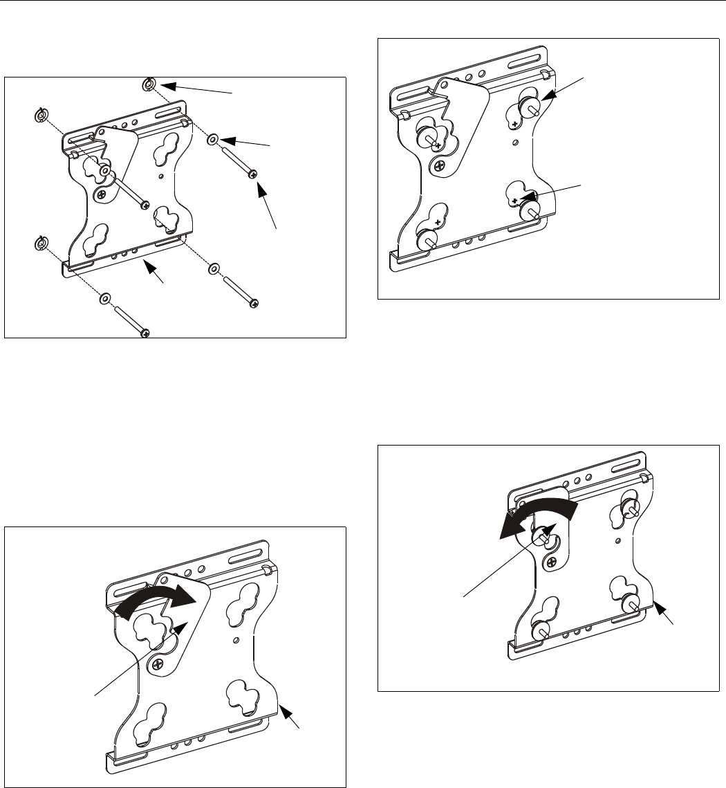
INSTALL DISPLAY TO MOUNT
NOTE: Proper interface must be attached to display. See
instructions that come with interface assembly.
1. Open latching flag by rotating flag clockwise on plate
(10) (See Figure 5).
Figure 5: Open Latching Flag
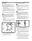
2. Lift and maneuver display such that all buttons fit into
button openings on plate (10). Lower display firmly
into place. Ensure each button has fully seated in its
button opening (See Figure 6).
NOTE: Mounting buttons are shown in the 100mm x
100mm pattern. Plate (10) will also accomodate
a 75mm x 75mm pattern.
Figure 6: Install Display to Plate
3. Close latching flag by rotating flag counterclockwise
on plate (10) (See Figure 7).
NOTE: An optional padlock may be used to secure
latching flag.
Figure 7: Close Latching Flag
4. Connect cables to display as required.
REMOVE DISPLAY FROM MOUNT
1. Disconnect all cables from display.
2. Open latching flag by rotating flag clockwise on plate
(10) (See Figure 5).
3. Lift and maneuver display mounting buttons out of
button openings.
(20)
(4 places)
(30)
(4 places)
Anchor Screw
(4 places)
(10)
(10)
Latching
Flag
NOTE: Display not shown for clarity.
Button location for
100mm x 100mm
pattern (4 places)
Button location for
75mm x 75mm
pattern (4 places)
NOTE: Display not shown for clarity.
(10)
Latching
Flag