


HOT WATER SYSTEM
The optional add-in boiler which may
be fitted in the appliance has an
output sufficient for domestic hot
water heating. If the boiler is fitted
then the room heating will be
reduced.
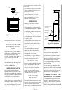
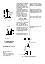
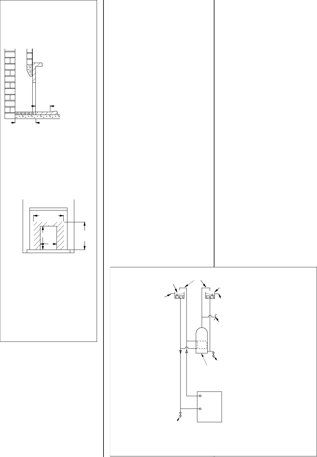
The hot water system should be a
gravity circuit and must be correctly
vented as shown in Fig. 6.
The steel boiler in conjunction with a
double feed indirect hot water storage
cylinder to BS:1566 part 1 should be
used in most situations, unless the
appliance is to be fitted in a soft
water area in which case the stainless
steel boiler may be used with a direct
hot water cylinder.
All pipework in the primary circuit
must be 28mm diameter and the flow
pipe must rise continuously from the
boiler to the open vent.
If an indirect cylinder is used then
the primary circuit should be filled
with a suitable inhibitor to prevent
the build up of scale and corrosion.
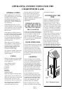
FITTING THE
OPTIONAL ADD-IN
BOILER
The boiler replaces the rear firebrick
and is reversible so that the 1’’
B.S.P. male tappings may come on
either the left or the right hand side
of the boiler.
The boiler tappings protrude from the
sides of the appliance and it will
therefore be necessary to fit the boiler
into the appliance after positioning
the appliance in the fireplace if the
fire surround is already fitted.
Before fitting the boiler, remove the
front firebars, the side and back fire
plates and the firebricks. Knock out
the knock-outs for the boiler tappings
on the appropriate side of the firebox.
Remove the backnuts and fibre
washers from the boiler tappings and
fit the boiler into the appliance. Place
the fibre washers over the tappings
on the outside of the appliance and fit
the backnuts, ensuring that the boiler
is held tightly against the rear inside
face of the appliance and that the top
edge of the boiler is level or runs
uphill to the flow tapping.
When re-fitting the firebricks, note
that the short side firebrick supplied
with the boiler must be fitted on the
same side as the boiler tappings. One
of the original side firebricks is fitted
on the other side, and the rear
firebrick is discarded. The firebricks
must be fire cemented into position,
wetting the firebox will improve the
adhesion.
Replace the back fireplate, the side
fireplates, the front firebar and the
throat plate.
Connect the boiler to the heating
system ensuring that the flow pipe
rises from the boiler. Fill the system
with water and check for leaks.
Drain Cock at Lowest Point
Drain Cock
Indirect Hot Water Cylinder
Cold Water Tank
Overflow
Feed and Expansion Tank
22mm Open Vents
Overflow
Domestic Hot Water Draw Off
Gravity Return 28mm
Gravity Flow 28mm
Fig. 6. Typical Gravity Hot Water System
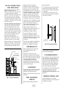
A
B
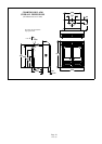
405 mm
400 mm
Minimum
This Dimension Is The
Minimum Level Area
Required To Enable The
For Overall Sizes Of
Hearth See The
Section Titled "Hearth".
Doors To Be Opened.
Fig. 4. Limiting Dimensions
Of Hearth
Dim. A:
Dim. B:
Min. 405mm (16")
660 mm
The shaded area on the face of
the surround is the minimum flat
area required.
750 mm
Min. 555mm (21 - 3/4")
Max. 575mm (22 - 2/3")
Max. 470mm (18 - 1/2")
Fig. 5. Limiting Dimensions Of
Surround And Opening
Page 8
LA20i 3/99