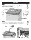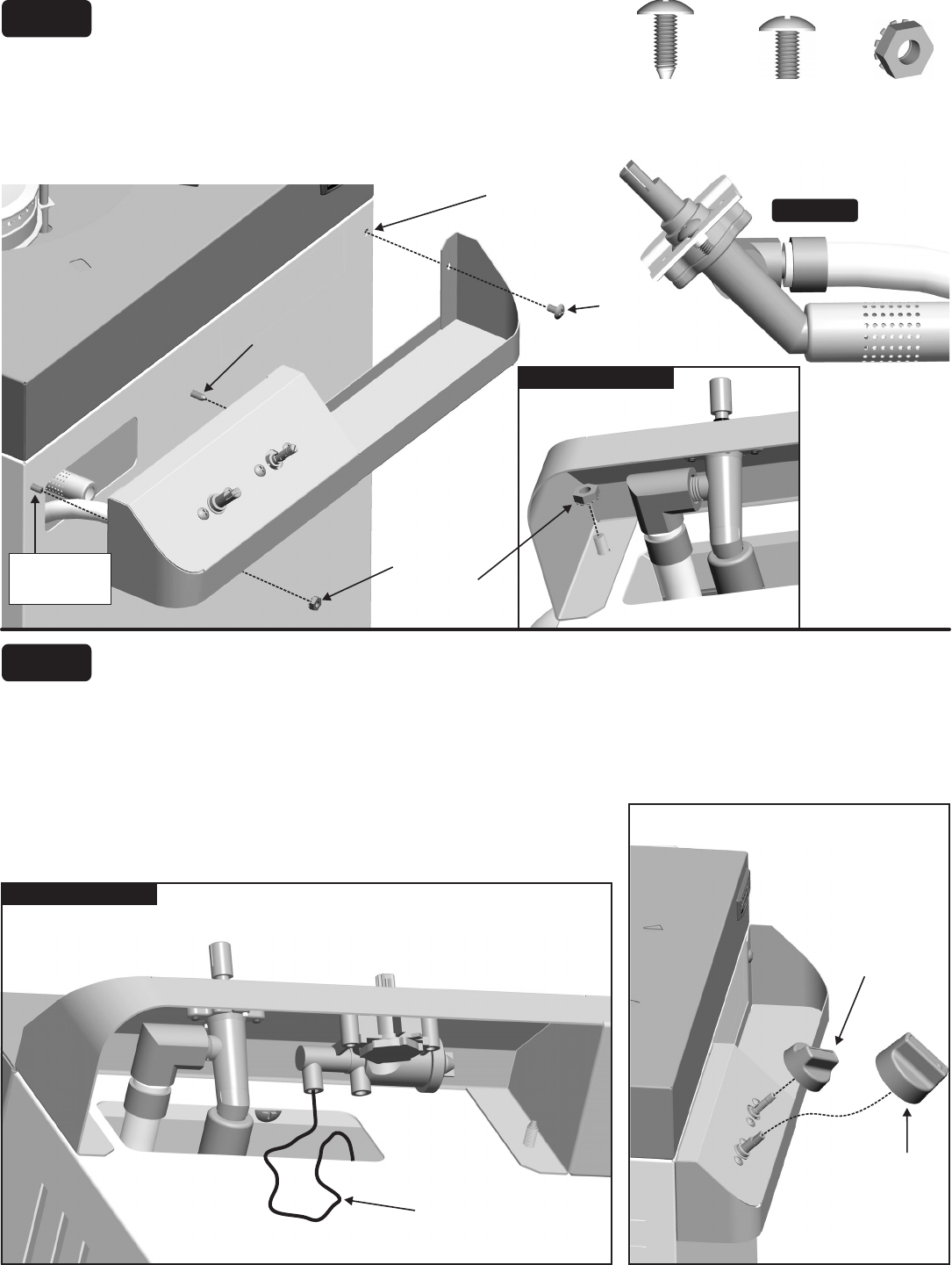
Step 5
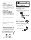
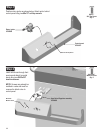
Align valve with burner tube. Figure A
#10-
24x3/8” machine screws #10-24 hex/keps nuts
#10x1/2” self-tap screw
See for proper valve-to-burner
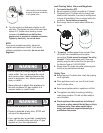
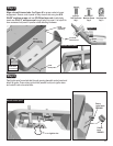
engagement. Secure control panel to body at each end using two
and two . Inside body,
insert one through body into panel. It is helpful to
have someone hold panel in position while attaching hardware.
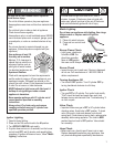
#10x1/2”
Self-Tap Screw
Qty: 1
#10-24x3/8”
Machine Screw
Qty: 2
#10-24
Hex/Keps Nut
Qty: 2
Figure A
Valve
Burner
Tube
Beneath control panel
#10-24
Hex/Keps Nut
inside body.
#10-24x3/8”
Machine Screw
#10x1/2”
Self-Tap Screw
from inside body
#10-24x3/8”
Machine Screw
from inside body
#10-24
Hex/Keps Nut
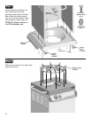
Step 6
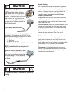
Feed ignitor wire from electrode through opening beneath control panel and
attach to ignitor. Press rotary ignitor knob (smaller knob) onto ignitor stem
and control knob onto valve stem.
Ignitor wire
Beneath control panel
Rotary
ignitor knob
29000950
Control
knob
29000951
15


