


Rev E Doc 01-20201 15 of 33
D. MASTER/SLAVE INTERCONNECTION
• A conduit between the Master and Slave units should be provided for the Master/Slave
interconnection cable.
• Two shielded twisted pair wire 16 AWG to 24 AWG will be connected between the two units at TB1
on the controller Board
NOTES: 1. Do not run the Master/Slave cable and AC power wires in the same conduit.
2. Master/Slave interconnection cabel should not exceed 3000 feet in length.
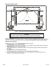
E. MASTER/SLAVE WIRING
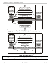
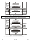
1. Select the desire gate layout in Section G.
2. Be sure to turn off BOTH gate operator units.
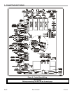
3. Wire all external control devices to their connection on the control board shown. See the Installation
and Operation instructions for the gate operators, Appendix A for details on how each control input
affects the gate operator.
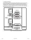
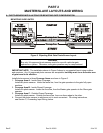
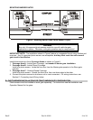
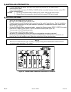
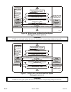
4. Connect the Master/Slave interconnect cable: connect the Receive inputs (RECV1, RECV2) on each
board to the Transmit inputs (XMIT1, XMIT2) on the other board (see Figure 10).
5. Turn on power to the Slave gate operator.
6. Turn on power to the Master gate operator.
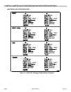
7. Set switch S1 on Master and Slave units to your configuration according to section F.
8. Perform the Post Assembly Procedure and the Final Assembly of Gate Operator instructions, as
found in Part 2 of the Installation and Operation instructions for the gate operators.
NOTE
Be sure to connect the two units correctly. Improper wiring of the Master/Slave interconnection
prevents proper operation of the system.
Figure 10. Master Slave Connection and Switch S1 Location.