


4
Planning
Identify the type and height of your garage door. Survey
your garage area to see if any of the conditions below
apply to your installation. Additional materials may be
required. You may fi nd it helpful to refer back to this page
and the accompanying illustrations as you proceed with
the installation of your opener.
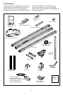
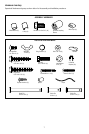
Depending on your requirements, there are several
installation steps which may call for materials or hardware
not included in the carton.
• Installation Step 1 – Look at the wall or ceiling above
the garage door. The header bracket must be securely
fastened to structural supports.
• Installation Step 4 – Depending upon garage
construction, extension brackets or wood blocks may
be needed to install sensors.
• Installation Step 4 – Alternate fl oor mounting of the
safety reversing sensor will require hardware not
provided.
• Installation Step 6 – Do you have a fi nished ceiling in
your garage? If so, a support bracket and additional
fastening hardware may be required.
• Do you have an access door in addition to the garage
door? If not, Model 7702CB Emergency Key Release is
required. See Accessories page.
• Look at the garage door where it meets the fl oor. Any
gap between the fl oor and the bottom of the door must
not exceed 1/4" (6 mm). Otherwise, the safety reversal
system may not work properly. See Adjustment Step 3.
Floor or door should be repaired.
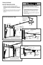
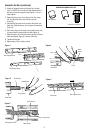
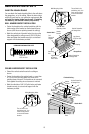
SECTIONAL DOOR INSTALLATIONS
• Do you have a steel, aluminum, fi berglass or glass
panel door? If so, horizontal and vertical reinforce ment
is required (Installation Step 12).
• The opener should be installed above the center of the
door. If there is a torsion spring or center bearing plate
in the way of the header bracket, it may be installed
within 4 feet (1.2 m) to the left or right of the door
center. See Installation Steps 1 and 12.
— — — — — — — —
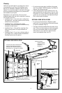
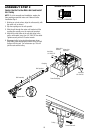
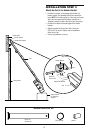
SECTIONAL DOOR INSTALLATION
Header Wall
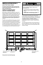
FINISHED CEILING
Horizontal and vertical reinforcement is
needed for lightweight garage doors
(fi berglass, steel, aluminum, door with
glass panels, etc.). See page 23 for details.
Support bracket &
fastening hardware
is required.
See page 19.
Motor unit
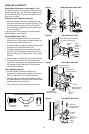
Extension
Spring
Vertical
Centerline
of Garage
Door
Wall-mounted
Door
Control
Gap between fl oor and bottom of
door must not exceed 1/4" (6 mm).
Torsion
Spring
OR
Access
Door
Safety Reversing Sensor
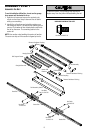
Rail
Safety Reversing Sensor
Trolley
Header
Bracket
Garage
Door
Spring
Emergency
Release
Rope &
Handle
Straight
Door Arm
Curved
Door Arm
Door
Bracket
Header
Wall
Garage
Door
Rail Bracket
CLOSED POSITION
Rail Assembly