


18
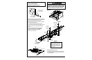
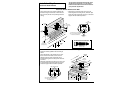
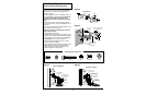
Installation Step 6
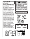
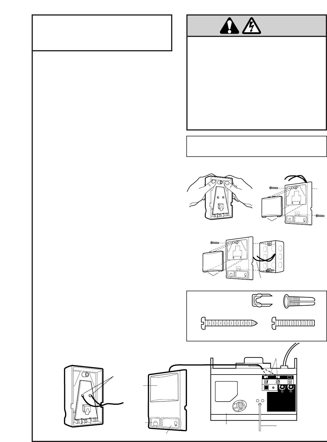
Install the Multi-Function
Door Control Panel
6ABx1-1/4" Screw
Multi-Function Door Control
Insulated Staples
Dry Wall Anchors
Screw 6-32x1"
Hardware Shown
Actual Size
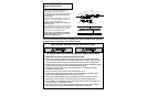
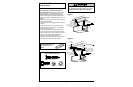
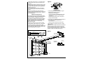
Outside Keylock Accessory Connections
To opener terminal screws: white to 2; white/red to 1
WARNING
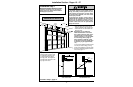
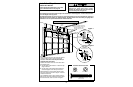
Door Control
Push Bar
Light Button
Lock
Button
2-Conductor
Bell Wire
Multi-Function
Door Control Panel
Terminal Screws
LOCK
LIGHT
2
1
RED
WHT
Opener
Terminal
Screws
Antenna
Back Panel
of Opener
KG
KG
1
3
9
7
5
1
3
9
7
5
2 3
1
DO NOT CONNECT TO LIVE ELECTRICAL WIRING.
CONNECT ONLY TO 24 VOLT LOW VOLTAGE
WIRES. CONNECTION TO LIVE WIRES OR HIGHER
VOLTAGE MAY CAUSE SERIOUS INJURY FROM
SHOCK, BURN OR ELECTROCUTION.
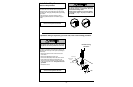
Children operating or playing with a garage door
opener can injure themselves or others.
The garage
door could close and cause serious injury or death.
Do not allow children to operate the push button(s)
or the remote control transmitter(s).
A moving garage door could injure someone under
it.
Activate the opener only when the door is
properly adjusted, you can see it clearly, and there
are no obstructions to door travel.
LOCK
LIGHT
To Replace,
Insert Bottom Tabs First
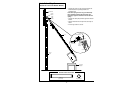
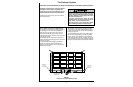
STANDARD WALL MOUNT
Locate the door control within sight of the door at
a minimum height of 5 feet where small children
cannot reach, and away from all moving parts of
the door and door hardware.
The multi-function door control is typically attached
directly to the wall. For pre-wired installations (as in
new home construction) it can be mounted to a
standard single gang box. See illustrations.
• Strip 1/4" of insulation from one end of the bell wire.
Connect the wire to the two screw terminals on the
back of the door control as follows: white wire to 2
and white/red wire to 1.
(NOTE: After installation, a
green indicator light behind the white translucent
cover will indicate proper connection. If not lit, the
Lock and Light features will not function (reverse
wires to correct).
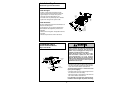
• Before mounting, remove the white cover by gently
pushing both thumbs against the upper corners of
the cover on the
back side
of the door control (see
illustration).
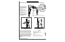
•
For standard wall mount,
mark the wall about 1-1/4"
up the centerline from the bottom of the door control.
Install a 6ABx1-1/4" self-tapping screw at this point,
allowing about 1/8" to protrude from the wall. Slip the
lower part of the door control over the screw head
and adjust for snug fit. Drill and install the top screw
with care to avoid cracking the plastic housing.
Do not
overtighten.
Run the bell wire up the wall and across
the ceiling to the opener. Use insulated staples to
secure the wire in several places. Be careful not to
pierce the wire with a staple, creating a short.
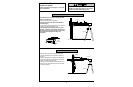
•
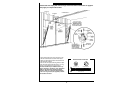
For pre-wired installations,
partially install a 6-32x1"
machine screw into the bottom of the gang box,
allowing about 1/8" to protrude. Slip the lower part of
the door control over the screw head and adjust for
snug fit. Install top screw with care to avoid cracking
plastic housing.
Do not overtighten.
• Connect the bell wire to the opener terminal screws
as follows: white to 2 and white/red to 1.
• Replace the cover by inserting bottom tabs and
snapping into place. To remove the cover after
mounting, gently pry at the top with a paper clip or
small flat head screwdriver.
2
1
RED
WHT
To Replace,
Insert Bottom Tabs First
PRE-WIRED INSTALLATION
24 Volt
2-Conductor Bell Wire
LOCK
LIGHT
REMOVE COVER