


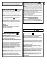
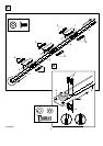
ADJUSTMENT SECTION –
LIMIT ADJUSTMENT –
Run the opener through a complete travel cycle. Limit adjustments
are not necessary when the door opens and closes completely and
doesn't reverse unintentionally in the fully closed position.
Situations requiring limit adjustment are listed below. Run the opener
through a complete travel cycle after each adjustment.
Note: Repeated operation of the opener during adjustment
procedures may cause motor to overheat and shut off. Allow a
15 minute cooling period after 5 continuous operations of the opener.
Read the following carefully before proceeding to Force Adjustment.
Use a screwdriver to make limit adjustments.
If Door Doesn't Open Completely but Opens at Least 1,5m (5 feet):
Increase up travel. Turn the up limit adjustment screw (1) clockwise.
One turn equals 5cm (2") of travel.
If door does not open at least 1,5m (5 feet): Adjust up (open)
force. See Force Adjustment.
If Door Doesn't Close Completely: If door arm is at maximum length,
increase down travel. Turn down limit adjustment screw (2)
counterclockwise. One turn equals 5cm (2") of travel. If the door still
will not close completely, the header bracket is positioned too high.
If Opener Reverses in Fully Closed Position: Decrease down
travel. Turn down limit adjustment screw (2) clockwise. One turn
equals 5cm (2") of travel.
If Door Reverses when Closing and there is no Interference to
Travel Cycle: Test door for binding. Pull manual release handle.
Manually open and close door. If door is binding, call a door
serviceman. If door is not binding or unbalanced, adjust
down (close) force.
22
PROGRAM YOUR OPENER & REMOTE –
Activate the opener only when door is in full view, free of
obstruction and properly adjusted. No one should enter or leave
garage while door is in motion. Do not allow children to operate
push button(s) or remote(s). Do not allow children to play near
the door.
Your garage door opener receiver and remote control transmitter are
set to a matching code. If you purchase additional remote controls, the
garage door opener must be programmed to accept the new remote
code.
Program the Receiver to Match Additional Remote Control Codes
1. Press and hold the remote control push button (1).
2. Press and release the "Smart" button (2) on the back panel of the
opener. The opener light will flash once.
3. Release the remote push button.
Now the opener will operate when the remote control push button is
pressed.
If you release the remote control push button before the opener
light flashes, the opener will not accept the code.
To Erase all Remote Control Codes
• Press and hold the "Smart" button on the opener panel until the
indicator light turns off (about 6 seconds). All the codes the opener
has learned will be erased.
• To reprogram, repeat Steps 1 – 3 for each remote control in use.
21
INSTALL THE LIGHT AND LENS –
Install a 40 watt maximum (230V, E27) light bulb (1) in the socket as
shown. The light will turn on and remain lit for 4-1/2 minutes when
power is connected. After 4-1/2 minutes it will turn off.
Replace burned out bulbs with rough service light bulbs. Bulb not
included. Use only 40 watt maximum (230V, E27) ESRS type.
Apply slight pressure on sides of the lens (2) and slide tabs (3) into
slots (4) in the end panel. Reverse the procedure to remove the lens.
FASTEN DOOR BRACKET –
If yours is a canopy or dual-track style garage door, a door arm
conversion kit is required. Follow the installation instructions included
with the replacement door arm. Exercise care in removing and
assembling arm conversion kit. Keep fingers away from the sliding
parts.
Sectional and One-Piece Door Installation Procedure:
1. Center bracket (1) at the top of inside face of door as shown.
Mark holes.
2. A. Wooden doors
Drill 8mm (5/16") holes and fasten the door bracket with nut,
lock washer, and carriage bolt (2).
B. Sheet metal doors
Fasten with sheet metal screws (3).
C. One-piece door optional
Fasten with sheet metal screws (3).
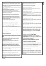
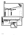
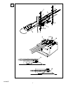
CONNECT DOOR ARM TO TROLLEY –
Sectional Door Installation: Note door arm configuration in Figure B.
One-Piece Door Installation: Procedure (Figure A).
Connect straight door arm (1) and curved door arm sections (2) to
obtain the longest possible length with hardware (3, 4 & 5). With door
closed, connect straight door arm section to door bracket with a
clevis pin (6). Secure with a ring fastener (7).
Before connecting door arm to trolley, adjust travel limits. Limit
adjustment screws are located on left side panel.
Open Door Adjustment: Decrease up limit. Turn up limit adjustment
screw counterclockwise 5-1/2 turns.
Press door control button. Trolley will travel to full open position (8).
Manually raise door to open position (parallel to floor) and lift
door arm (9) to trolley. The arm should touch trolley just in back of
door arm connector hole (10) as shown in solid line drawing. Increase
up limit if necessary. One full turn equals 5cm (2") of door travel.
Closed Door Adjustment: Decrease down limit. Turn down limit
adjustment screw clockwise 5 complete turns.
Press door control button. Trolley will travel to full closed position (11).
Manually close door and lift door arm (12) to trolley. The arm should
touch trolley just ahead of door arm connector hole (13) as shown in
dotted line drawing. Decrease down limit if necessary. One full turn
equals 5cm (2") of door travel.
Connect Door Arm to Trolley: With door closed, connect curved arm
to trolley with remaining clevis pin. Secure with ring fastener.
Note: Lift door slightly to make connection if necessary.
Run opener through a complete travel cycle. If door has a slight
"backward" slant in full open position, decrease up limits until door is
parallel to floor.
20
19
18
22 24
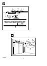
OPERATION OF THE LIGHTED DOOR CONTROL BUTTON
Press to open or close the door. Press again to reverse the door
during the closing cycle or to stop the door during opening cycle.
4-GB
114A2062H