


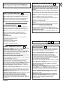
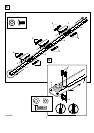
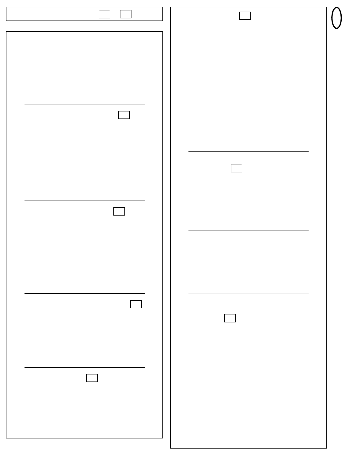
HANG THE OPENER –
The opener must be securely fastened to a structural support of
the garage.
Three representative installations are shown. Yours may be
different. Hanging brackets (1) should be angled (Figure A) to
provide rigid support. On finished ceilings, (Figure B) attach a sturdy
metal bracket (not supplied) (4) to a structural support before installing
the opener. For concrete ceiling mount, (Figure C), use concrete
anchors (5) provided.
On each side of opener measure the distance from the opener to the
structural support (or ceiling).
Cut both pieces of the hanging bracket to required lengths. Flatten one
end of each bracket and bend or twist to fit the fastening angles. Do
not bend at the bracket holes. Drill 4,5mm (3/16") pilot holes in the
structural supports (or ceiling). Attach flattened ends of brackets to
supports with wood screws (2).
Lift opener and fasten to hanging brackets with screw, lock washer
and nut (3). Check to make sure T-rail is centered over the door.
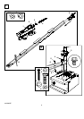
REMOVE 25mm (1") board. Operate door manually. If door hits the
rail, raise header bracket.
Grease the top and underside of rail surface on which the trolley
slides. A tube of grease is supplied.
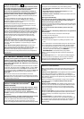
ATTACH MANUAL RELEASE
ROPE & HANDLE –
Thread one end of rope (1) through hole in top of red handle so
"NOTICE" reads right side up as shown (3). Secure with an overhand
knot (2). Knot should be at least 25mm (1") from end of the rope to
prevent slipping.
Thread other end of rope through hole in release arm of the outer
trolley (4). Adjust rope length so that handle is 1,8m (6 feet) above the
floor. Secure with an overhand knot.
Note: If it is necessary to cut rope, heat seal cut end with a match
or lighter to prevent fraying.
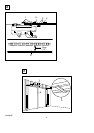
CONNECT ELECTRIC POWER
TO AVOID INSTALLATION DIFFICULTIES, DO NOT RUN THE
GARAGE DOOR OPENER UNTIL INSTRUCTED TO DO SO.
Connect the opener to a mains which is properly EARTHED
according to the wiring instruction tag attached to power supply
cord (and as specified by local code).
Connect the door opener only to an outlet controlled by a double
pole switch.
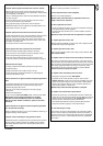
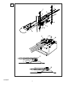
INSTALL THE MULTI-FUNCTION DOOR CONTROL
(MOTORLIFT 5000) OR LIGHTED DOOR CONTROL
PUSH BUTTON –
Locate the door control within sight of the garage door, away
from all moving parts of the door and door hardware and out of
the reach of children.
Serious personal injury from a moving garage door may result
from misuse of opener. Do not allow children to operate the door
control or remote control transmitters.
Fasten the caution label on the wall near the door control as a
reminder of safe operating procedures.
There are 2 screw terminals (1) on the back of the multi-function door
control (2), or lighted door control button (3). Strip about 6mm (1/4") of
insulation from bell wire (4). Separate wires enough to connect the
white/red wire to terminal screw 1 and the white wire to terminal screw 2.
Fasten the multi-function door control to an inside garage wall with
sheet metal screws provided (5). For lighted door control button use
screws provided (6). Drill 4mm (5/32") holes and use anchors (7) if
installing into drywall or concrete. A convenient place is beside the
service door and out of reach of children.
Run the bell wire up the wall and across the ceiling to the garage door
opener. Use insulated staples (8) to secure wire. The receiver terminal
screws (9) are located on the back panel of the opener. Connect the bell
wire to the terminal screws as follows: white/red to 1 and white to 2.
17
16
15
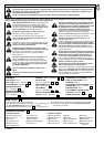
Wear protective goggles when working overhead to protect your
eyes from injury.
Disengage all existing garage door locks to avoid damage to the
garage door.
To avoid serious personal injury from entanglement, remove all
ropes connected to the garage door before installing the opener.
Installation of this product shall comply with ZH1/494, VDE 0700
Part 238, and VDE 0700 Part 1.
It is recommended that the opener be installed 2,1m (7 feet) or more
above the floor where space permits.
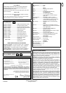
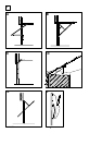
POSITION THE HEADER BRACKET –
The header bracket must be rigidly fastened to a structural
support of the garage. Reinforce the wall or ceiling with a
40mm (1-1/2") board if necessary. Failure to comply may result in
improper operation of safety reverse system.
You can attach the header bracket either to the header wall (1) or to
the ceiling (3). Follow the instructions which will work best for your
particular requirements.
With the door closed, mark the vertical centerline (2) of the garage
door. Extend line onto header wall above the door.
Open door to highest point of travel. Draw an intersecting horizontal
line on header wall 5cm (2") above high point to provide travel
clearance for top edge of door.
INSTALL THE HEADER BRACKET –
A. Wall Mount: Center the bracket (2) on the vertical guideline (1)
with the bottom edge of the bracket on the horizontal line (6)
(with the arrow pointing toward the ceiling).
Mark either set of bracket holes (4 or 5). Do not use the holes
designated for ceiling mount. Drill 4,5mm (3/16") pilot holes and
fasten the bracket with wood screws (3).
B. Ceiling Mount: Extend vertical guideline (1) onto the ceiling.
Center the bracket (2) on the vertical mark no more than 150mm (6")
from the wall. Make sure the arrow is pointing toward the wall.
Mark holes designated for ceiling mount only (4). Drill 4,5mm (3/16")
pilot holes and fasten the bracket with wood screws (3).
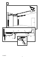
ATTACH T-RAIL TO HEADER BRACKET –
Position opener on garage floor below the header bracket. Use
packing material to protect the cover.
Note: To enable the T-rail to clear sectional door springs, it may be
necessary to lift opener onto a temporary support.
The opener must either be secured to a support or held firmly in place
by another person.
Raise T-rail until cable pulley and header brackets come together.
Join with clevis pin (1). Insert ring fastener (2) to secure.
POSITION THE OPENER –
Note: A 25mm (1") board (1) is convenient for setting an ideal
door-to-T-rail distance (unless headroom is not sufficient).
Raise the opener onto a stepladder. Open garage door. Place a
25mm (1") board (1) laid flat on the top section of door near the
centerline as shown. Rest the T-rail on the board.
If the raised door hits the trolley, pull down on the trolley release arm
to disconnect the inner and outer trolley sections. The trolley can
remain disconnected until connecting door arm to trolley is completed.
14
13
12
11
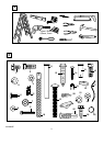
INSTALLATION SECTION –
11 20
3-GB
114A2062H