


9
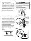
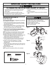
WHT/GRN
To insert or release wire,
push in tab with
screwdriver tip
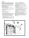
Cable Tension
Monitor
7/16" (11mm)
Strip wire 7/16" (11mm)
WHT/GRN
Cable
Tension
Monitor
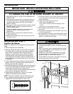
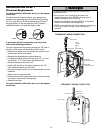
Cable Tension
Monitor Roller
Cable
2"-6"
(5 cm-
15 cm)
Drum
Torsion Bar
Opener
1/8"-1/4"
(3 mm-6 mm)
With Door Closed
Preferred Orientation
Figure 1
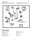
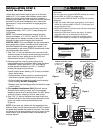
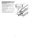
#8 Hex Head Screw (2)
Screw #6 (2) Wall Anchor (2)
Staples
HARDWARE SHOWN ACTUAL SIZE
Figure 3
INSTALLATION STEP 4
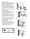
Attach the Cable Tension Monitor
(Required)
This opener comes standard with the cable tension
monitor. It is supplied as a device to monitor the
cables for ANY slack that may occur and will reverse
the door when excessive slack is detected, eliminating
service calls.
The cable tension monitor MUST be connected and
properly installed before the garage door opener will
move in the down direction.
NOTE: The cable tension monitor is shipped for left side
installation. It is preferred that the cable tension monitor
be installed on the same side of the door as the opener. If
required, it can be mounted on the opposite side of door.
Remove the snap-ring holding the roller in place and
reassemble it on the opposite side of the cable tension
monitor.
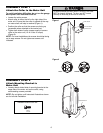
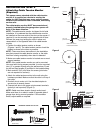
1. Position the cable tension monitor as shown
(Figures 1 and 2). The cable tension monitor should be
located as close to the drum as possible.
NOTE: There must be no obstructions in the installation
area that prevent the cable tension monitor or the cable
itself from closing completely when slack is detected.
2. Make sure cable tension monitor is located over a wood
support member.
NOTE: If the cable tension monitor can not be mounted
into wood with the lag screws provided, it can be mounted
into 1/2" or greater drywall using the wall anchors (2) and
the #8 hex head screws (2) provided in the hardware bag.
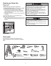
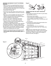
3. Mark and drill 3/16" pilot holes for screws (pilot holes
are not required for anchors).
4. Attach the cable tension monitor to the wall using the
hardware provided. Make sure that the roller is on top of
the cable.
5. Run bell wire to motor unit. Use insulated staples to
secure wire in several places.
6. Connect bell wire to the green quick-connect terminals
(polarity is not important) (Figure 3).
NOTE: Cable must have tension through entire travel.
Make sure there is no slack in cable on opposite side of
garage door during normal operation. If this condition
exists, adjust cables as required.
3/4" Min.
(18 mm Min.)
Wall
Drum
Cable
Figure 2