


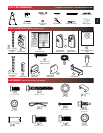
Mounting Straps
[22]
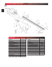
13
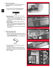
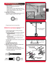
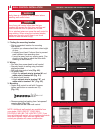
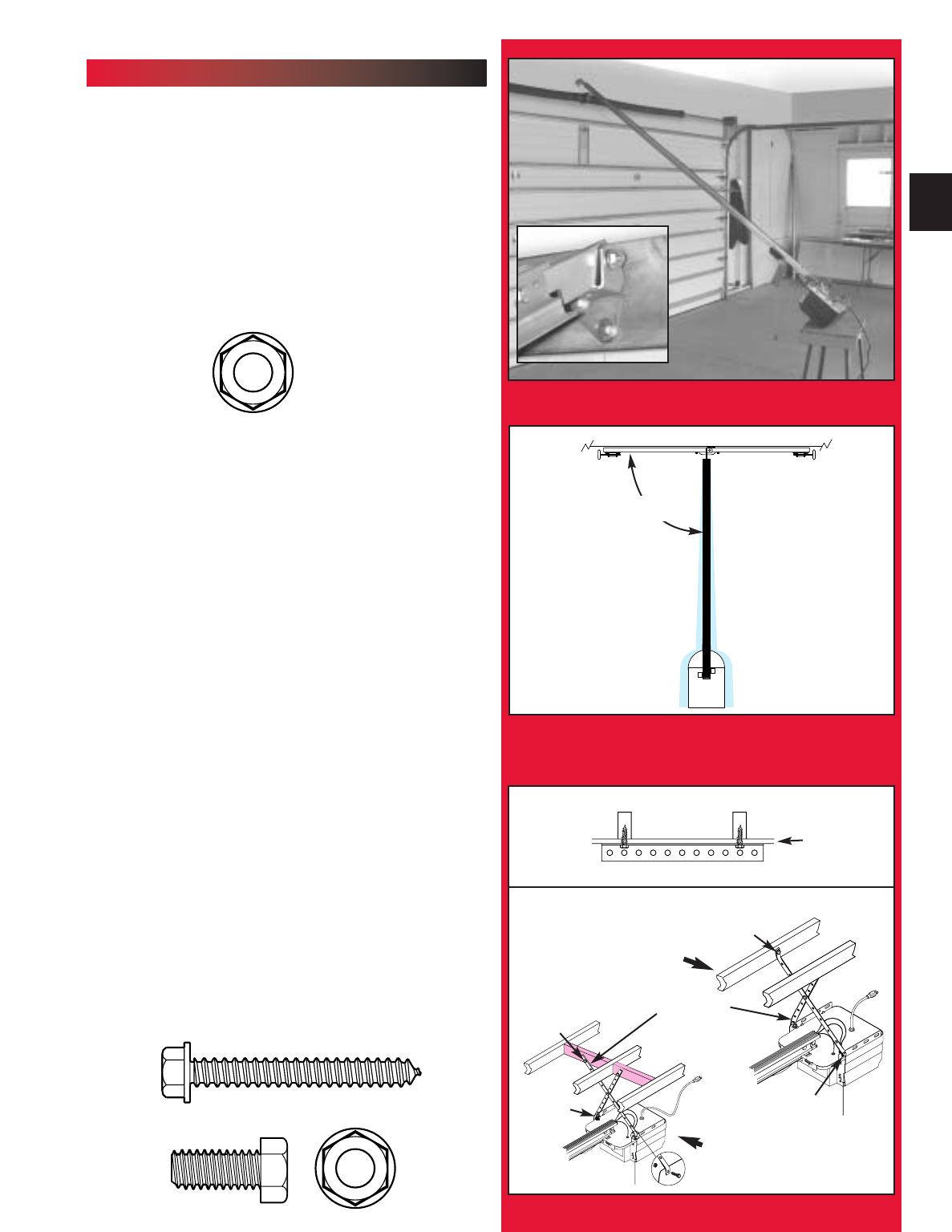
MOUNTING THE OPERATOR:
1. Getting Started.
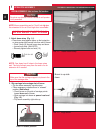
• Position boom/power head assembly (Fig. 2-7).
–
Boom strap leaning on wall next to
header bracket.
– Place material on floor under power head to
protect from scratching. (A box, stool, or similar
device may be needed to clear a torsion
spring, as shown.)
2. Mounting the assembly.
•
Attach boom strap to header bracket using nut (47)
(Fig. 2-7 inset)
.
FINGER TIGHT ONLY.
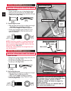
• Support power head on step-ladder.
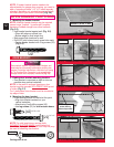
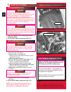
NOTE: Before final attachment to ceiling, insure that
assembly is in proper alignment (Fig. 2-9).
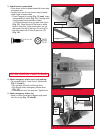
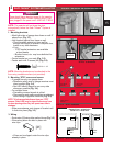
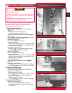
• Attach mounting straps to ceiling using lag
bolts (22) (Fig. 2-10).
• Set height of power head according to following:
– Track guided doors
.
-Boom must clear door at highest point of
travel.
- Be level or, power head slightly below level.
– Trackless doors
.
-Boom must clear door at highest point of
travel by 1" to 1-1/2".
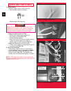
• Securely tighten power head mounting bolts (46)
and nuts (47).
• Lower door.
• Fully tighten boom strap nut.
• DO NOT PLUG UNIT IN YET!
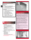
3. Adjusting length of emergency release cord.
• Check release knob height.
– Low enough you can reach it.
– High enough to clear your vehicle, but
NO HIGHER THAN 6 FEET ABOVE FLOOR.
• Tie a new overhand knot where desired.
– Cut off any extra cord.
YES
N
O
N
O
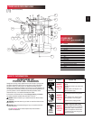
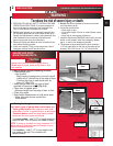
FIG. 2-10 Mounting the power head.
ANGLE IRON ON FINISHED CEILING
Attach angle iron to beams
UNFINISHED OR OPEN BEAM
Extra framing
not needed
Extra framing
NEEDED
VIEW FROM ABOVE
(not to scale)
[22]
[
22
]
[
46
]
[
47
]
[
47
]
90°
DOOR
HEADER BRACKET
DRYWALL
[46 & 47]
[46 & 47]
5/16"-18
5/16"-18 x 3/4"
5/16"-18
1/4" x 2"
FIG. 2-7 Position assembly.
FIG. 2-9 Operator must be aligned.