


15
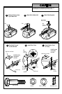
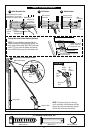
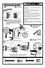
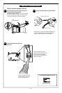
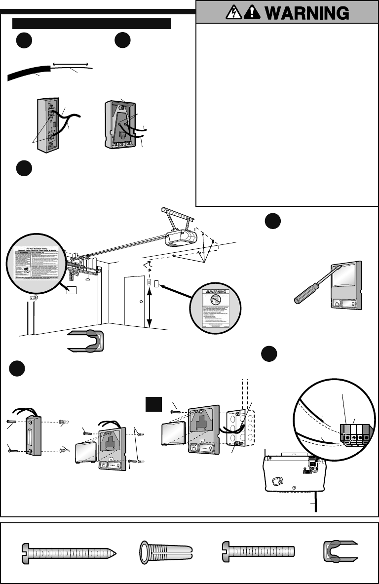
INSTALLING THE DOOR CONTROL
1
3
5
4
6
2
ALL HARDWARE SHOWN ACTUAL SIZE
C10 Screw C13 Drywall Anchors C11 Screw C1 Insulated Staples
Multi-Function Door Control:
Gang Box Installation
Multi-Function Door Control:
If, No Gang Box is Present
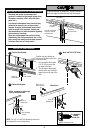
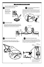
Position Door Control, Route Door Control
Wire to Motor Unit and Secure with Insulated
Staples. Permanently Mount 2 Safety Labels
Using Adhesive Backing, Tacks or Staples,
If Necessary.
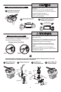
LOCK
LIGHT
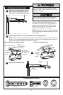
Carefully Remove Cover
Multi-Function Door
Controls ONLY
Connect Door Control Wires
to Motor Unit
Attach Door Control to Wall and Replace Cover
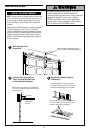
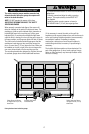
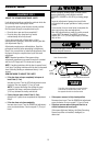
To prevent possible SERIOUS INJURY or DEATH from
electrocution:
• Be sure power is NOT connected BEFORE installing
Door Control.
• Connect ONLY to 24 VOLT low voltage circuit.
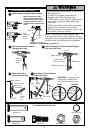
To prevent possible SERIOUS INJURY or DEATH from a
closing garage door:
• Install Door Control within sight of garage door, out of
reach of children at a minimum height of 5 feet
(1.5 m), and away from ALL moving parts of door.
• NEVER permit children to operate or play with door
control push buttons or remote controls.
• Activate door ONLY when it can be seen clearly, is
properly adjusted, and there are no obstructions to
door travel.
• ALWAYS keep garage door in sight until completely
closed. NEVER permit anyone to cross path of closing
garage door.
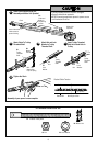
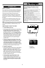
Connect Wire
to Door Control
Strip Door Control Wire
To release or
insert wire,
push in tab with
screwdriver.
OR
Strip 7/16" (11 mm)
Insulation
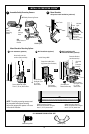
Wire
Red Terminal
White
Terminal
Antenna
Red/White
Wire
White Wire
A21 Door Control
Button
Terminal
Screws
Do NOT strip any
insulation from the staples
C1
Insulated
Staple
C1
Insulated Staple
Door Control
Wire
5 FEET
(1.5 m)
MINIMUM
Door Control Button Multi-Function
Door Control
C11 Screw
C11
Screw
Single Gang Box
C13
Drywall
Anchors
C13
Drywall
Anchors
24V
Circuit
C10
Screw
C10
Screw
C10
Screw
Terminal
Screws
White
Wire
A6 Door Control: Multi-Function
Red/White
Wire
Red/White Wire
White Wire