


• Position the template horizontally to match up the
centerlines of the header bracket and the template.
Refer to Figure 8 or Figure 9, depending on your door
style.
• To check, place the extension arm on the trolley into
the slot on the template. The extension arm should be
straight and in line with the garage door operator rail.
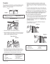
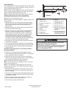
Note: The door arm should extend about 13mm (1/2”)
over the top of the door (Figure 10 or Figure 11). If
not, check template and hole positions.
• Select and mark the (2) template holes which will allow
the mounting screws the best possible support in the
door, (preferable hole locations into the door’s main
bracing) as shown in Figures 10/11.
If possible, use
additional screws.
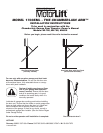
The garage door may require additional bracing to
provide suitable support.
4
Template
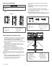
The template is provided for use with two different types
of doors. Position and mark holes as directed below,
based on your requirements.
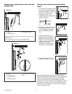
Door without a Lip
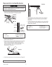
• Bend back tabs on the template (Figure 7).
• Rest the bottom of the tabs on the top of the door as
shown in Figure 8 (door without a lip). This provides
proper vertical replacement of holes.
Door with a Lip
• For a door with a lip, as shown in Figure 9, do not
bend back the tabs on the template. Instead, position
the horizontal dotted line at the top of the lip.
This
provides proper vertical placement of the holes.
Tem
plate
1
2
1
3
FIGURE 7
Figure 11
Figure 12
12
3
4
5
6
1
2
3
4
5
6
Figure 11
Figure 12
1
2
3
4
5
6
1
2
3
4
5
6
FIGURE 10
FIGURE 11
1
2
3
4
5
FIGURE 8
Figure 10
1
3
6
5
7
8
FIGURE 9
1. Tab
2.
Centerline of Template
3. Slot for Extension Arm
Alignment Test
1.
Centerline of Header
Bracket
2.
Tab
3.
T
emplate
4. Canopy Door without
Lip
5. Extension
Arm
6. Canopy Door with Lip
7.
T
op of
T
emplate for
Door with Lip
8. Top of Door with Lip
1.
T
op of Canopy Door
without Lip
2. 13mm (1/2”)
3.
T
op of Door
Arm
4. Screws
5. Use additional screws if
possible
6. Door
Arm
114A3167A-GB