


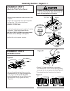
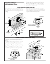
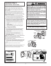
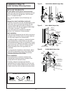

Outside Keylock Accessory Connections
To opener terminal screws: white to 2; white/red to 1
WARNING
DO NOT CONNECT TO LIVE ELECTRICAL WIRING.
CONNECT ONLY TO 24 VOLT LOW VOLTAGE
WIRES. CONNECTION TO LIVE WIRES OR HIGHER
VOLTAGE MAY CAUSE SERIOUS INJURY FROM
SHOCK, BURN OR ELECTROCUTION.
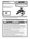
Children operating or playing with a garage door
opener can injure themselves or others. The garage
door could close and cause serious injury or death.
Do not allow children to operate the push button(s)
or the remote control transmitter(s).
A moving garage door could injure someone under
it. Activate the opener only when the door is
properly adjusted, you can see it clearly, and there
are no obstructions to door travel.
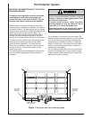
Do NOT connect the power and operate the
opener at this time.
The trolley will travel to the
full
open
position but will not return to the
close
position until the sensor beam is connected and
properly aligned. See Safety Reversing Sensor
Instructions beginning on page 17.
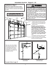
Installation Step 6
Install the Door Control Panel
14
Opener
Terminal Screws
Antenna
RIGHT PANEL OF OPENER
KG
KG
1
3
9
7
5
1
3
9
7
5
2 3
1
2-Conductor
Bell Wire
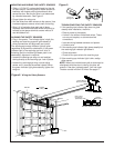
Push Bar
Light Button
Lock
Button
LOCK
LIGHT
1
RED
2
WHITE
Door
Control
Terminal
Screws
2-Conductor
Bell Wire
LOCK
LIGHT
To Replace
Insert Top
Tabs First
STANDARD WALL MOUNT
Detector
Switch
Push Bar Cover
ON
OFF
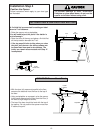
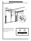
Locate the door control within sight of the door at a
minimum height of 5 feet where small children cannot
reach, and away from all moving parts of the door and
door hardware.
The door control is typically attached directly to the wall.
If installing into drywall, drill 5/32" holes and use the
anchors provided. For pre-wired installations (as in new
home construction) it can be mounted to a standard single
gang box. See illustrations.
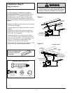
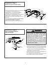
1. Strip 1/4" of insulation from one end of the bell wire.
Connect the wire to the two screw terminals on back of
door control: white wire to 2 and white/red wire to 1.
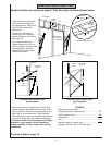
2. Remove the push bar cover by gently prying off the top
edge with a coin or screwdriver. Fasten with 6ABx1-1/4"
self-tapping screws (standard installation) or 6-32x1"
machine screws (pre-wired installation) as follows:
• Install bottom screw, allowing 1/8" to protrude from
the wall.
• Position bottom of door control on screw head and
adjust for snug fit.
• Install top screw with care to avoid cracking plastic
housing.
Do not overtighten.
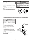
3. (For standard wall mount only)
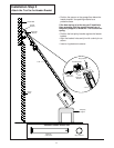
Run the bell wire up wall and across ceiling to opener.
Use insulated staples to secure the wire in several
places. Be careful not to pierce the wire with a staple,
creating a short.
4. Connect the bell wire to the terminal screws on the
opener panel: white to 2 and white/red to 1.
5. After testing, replace the cover by inserting top tabs
and snapping into place.
NOTE: After installation, the green indicator light behind the
push bar cover will indicate proper connection.
The automatic light feature will become functional 1-1/2
minutes after power is restored.
6. Attach the User Safety Instruction label to the wall near
the door control, and the Maintenance Instruction label
in a prominent location on the inside of the garage
door.
Page 28 explains how to use the door control.
This device complies with Part 15 of the FCC Rules. Operation is subject to
the following two conditions: (1) this device may not cause harmful
interference, and (2) this device must accept any interference received,
including interference that may cause undesired operation.
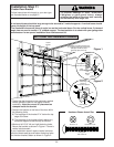
24 Volt
2-Conductor Bell Wire
PRE-WIRED INSTALLATION
LOCK
LIGHT
To Replace
Insert Top
Tabs First
Detector
Switch
Push Bar Cover
ON
OFF
6ABx1-1/4" Screw
(std installation)
Insulated
Staples
Dry Wall Anchors
Screw 6-32x1" (pre-wired)
Hardware Shown
Actual Size