


18
To prevent possible SERIOUS INJURY or DEATH from
electrocution:
• Be sure power is not connected BEFORE installing door
control.
• Connect ONLY to 24 VOLT low voltage wires.
To prevent possible SERIOUS INJURY or DEATH from a
closing garage door:
• Install door control within sight of garage door, out of
reach of children at a minimum height of 5 feet (1.5 m),
and away from all moving parts of door.
• NEVER permit children to operate or play with door
control push buttons or remote control transmitters.
• Activate door ONLY when it can be seen clearly, is
properly adjusted, and there are no obstructions to door
travel.
• ALWAYS keep garage door in sight until completely
closed. NEVER permit anyone to cross path of closing
garage door.
WARNING
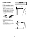
CAUTION
WARNING
WARNING
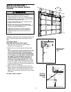
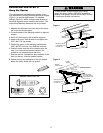
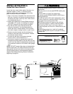
Drywall Anchors
Insulated
Staples
Screw 6ABx1-1/2"
Lighted Door Control Button
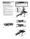
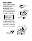
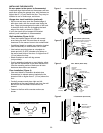
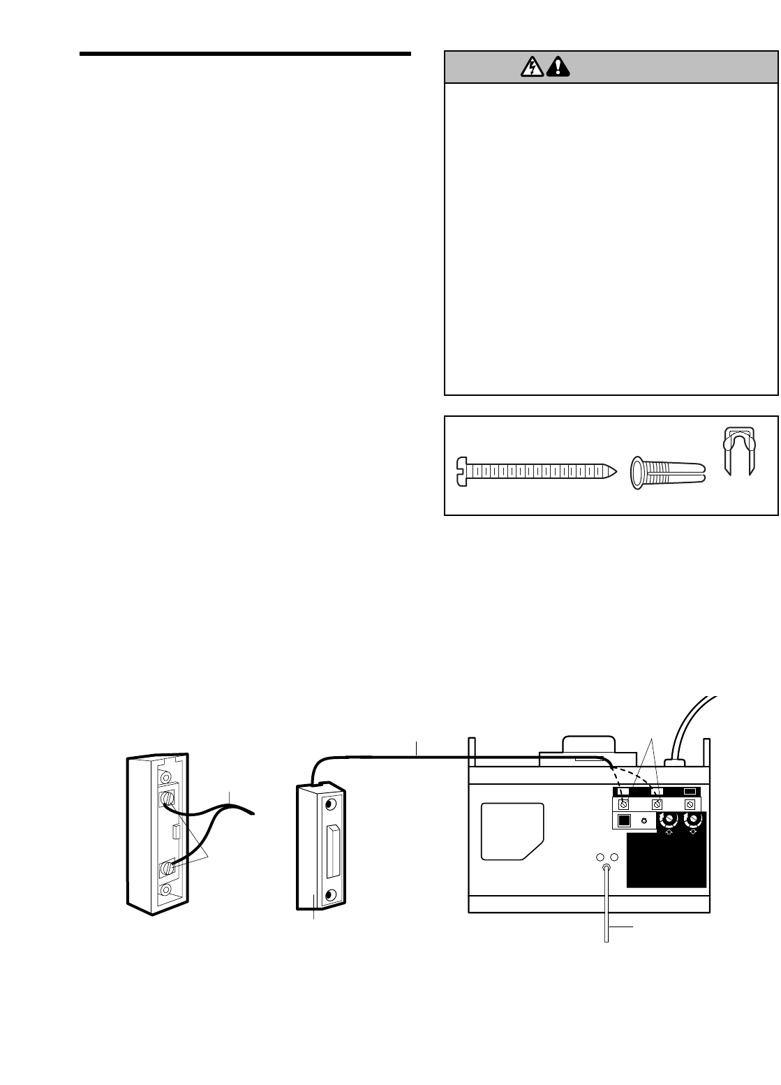
INSTALLATION STEP 6
Install the Door Control
Locate the door control within sight of the door at a
minimum height of 5 feet (1.5 m) where small
children cannot reach, and away from all moving
parts of the door and door hardware.
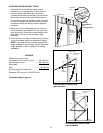
1. Strip 1/4" (6 mm) of insulation from one end of the
bell wire. Connect it to the two screw terminals on
the back of the door control by color: white wire to
2 and white/red wire to 1.
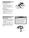
2. Fasten the Lighted Door Control Button securely
with 6ABx1-1/2" screws. If installing into drywall,
drill 5/32" holes and use the anchors provided.
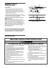
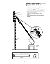
3. Run the bell wire up the wall and across the
ceiling to the opener. Use insulated staples to
secure the wire in several places. Do not pierce
wire with a staple, creating a short or open circuit.
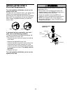
4. Receiver terminal screws and the antenna are
located on the back panel of the opener. Position
the antenna wire as shown.
5. Connect the bell wire to the opener terminal
screws: white to 2 and white/red to 1.
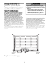
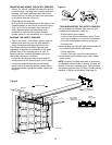
6. Use tacks or staples to permanently attach the
entrapment warning label to the wall near the door
control, and the manual release/safety reverse test
in a prominent location on the inside of the garage
door.
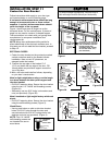
NOTE: DO NOT connect the power and operate the
opener at this time. The trolley will travel to the full
open position but will not return to the close position
until the sensor beam is connected and properly
aligned. See Safety Reversing Sensor instructions
beginning on page 21.
Opener
Terminal Screws
Bell Wire
Antenna
BACK PANEL
Lighted Door
Control Button
Terminal Screws
Bell Wire
WHT
RED
KG
KG
1
3
9
7
5
1
3
9
7
5
2 3
1
-2
-1
Lighted
Door Control Button
HARDWARE SHOWN ACTUAL SIZE