


22
ALL ONE-PIECE DOORS
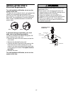
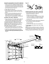
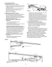
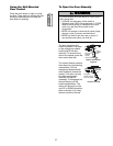
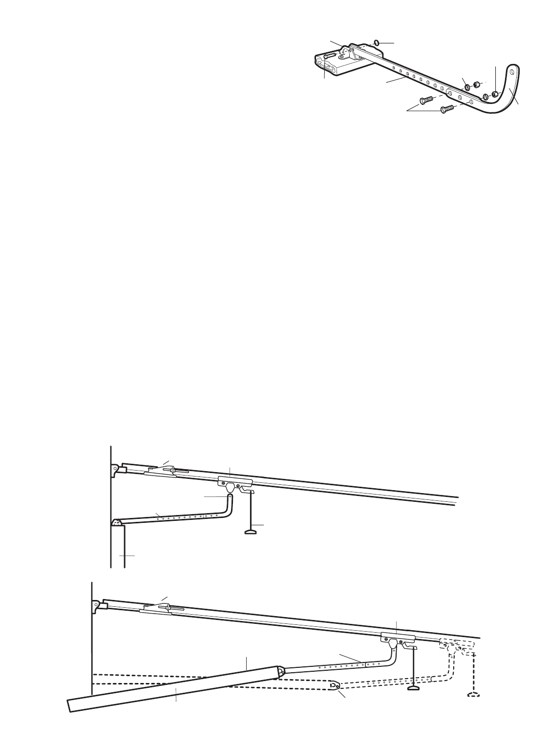
1. Assemble the door arm, Figure 4:
• Fasten the straight and curved door arm sections
together to the longest possible length (with a 2
or 3 hole overlap).
• With the door closed, connect the straight door
arm section to the door bracket with the
5/16"x1-1/4" clevis pin.
• Secure with a ring fastener.
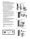
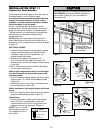
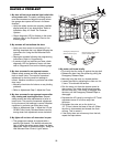
2. Adjustment procedures, Figure 5:
• On one-piece doors, before connecting the door
arm to the trolley, the travel limits must be
adjusted. Limit adjustment screws are located on
the left side panel as shown on page 23. Follow
adjustment procedures below.
• Open door adjustment: decrease UP
travel limit
- Turn the UP limit adjustment screw
counter-clockwise 4 turns.
- Press the Door Control push button. The trolley
will travel to the fully open position.
- Manually raise the door to the open position
(parallel to the floor), and lift the door arm to the
trolley. The arm should touch the trolley just in
back of the door arm connector hole. Refer to
the fully open trolley/door arm positions in the
illustration. If the arm does not extend far
enough, adjust the limit further. One full turn
equals 2" (5 cm) of trolley travel.
• Closed door adjustment: decrease DOWN
travel limit
- Turn the DOWN limit adjustment screw
clockwise 4 complete turns.
Nuts
5/16"-18
Lock
Washers
5/16"
Ring
Fastener
Straight
Arm
Bolts
5/16"-18x7/8
Door
Bracket
Clevis Pin
5/16"x1-1/4"
Curved
Door Arm
- Press the Door Control push button. The trolley
will travel to the fully closed position.
- Manually close the door and lift the door arm to
the trolley. The arm should touch the trolley just
ahead of the door arm connector hole. Refer to
the fully closed trolley/door arm positions in the
illustration. If the arm is behind the connector
hole, adjust the limit further. One full turn equals
2" (5 cm) of trolley travel.
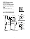
3. Connect the door arm to the trolley:
• Close the door and join the curved arm to the
connector hole in the trolley with the remaining
clevis pin. It may be necessary to lift the door
slightly to make the connection.
• Secure with a ring fastener.
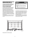
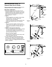
• Run the opener through a complete travel cycle. If
the door has a slight "backward" slant in full open
position as shown in the illustration, decrease the
UP limit until the door is parallel to the floor.
NOTE: When setting the up limit on the following
page, the door should not have a "backward" slant
when fully open as illustrated below. A slight
backward slant will cause unnecessary bucking
and/or jerking operation as the door is being opened
or closed from the fully open position.
Figure 4
Door Arm
Door Arm
Connector Hole
Closed
Door
Outer Trolley
Emergency Release Handle
Inner Trolley
Outer Trolley
Open Door
Door Arm
Correct Angle
Door with
Backward Slant (Incorrect)
Inner Trolley
Figure 5