


PN# 3642036534, 02/26/2010 REV. 1
17
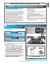
AFE-T-BEAM
®
SYSTEM INSTALLATION
FOR HELP-1.800.354.3643 OR WWW.GENIECOMPANY.COM
4
NOTE: The opener will not close the door
automatically unless the Safe-T-Beam
®
System is
installed.
NOTE: For Safe-T-Beam®, screws, wire, and
insulated staples locate items and Bag 8 from Box 3.
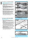
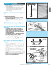
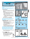
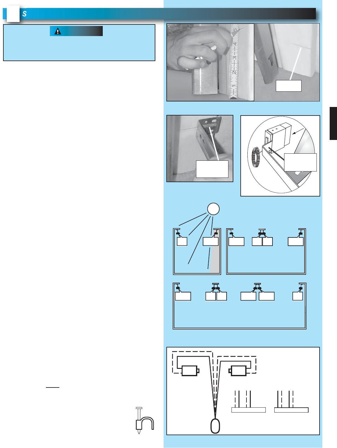
1. Mounting brackets.
Mark both sides of garage door frame or wall no
higher than 6" and no lower than 5" above floor
(Fig. 4-1)
.
Hold bracket against door frame or wall.
– Check if brackets extend out from wall far
enough, so tongue of bracket is beyond door,
tracks or any door hardware.
– If not:
a) Mounting bracket extensions are available
through an authorized Genie
®
Dealer.
b) Blocks of wood, etc. may be substituted for
extensions.
Center bracket on your mark (Fig. 4-2).
Fasten each with 2 screws (Fig. 4-2).
NOTE: Mounting brackets can be attached to the
floor or concrete rim using concrete anchors
(not provided).
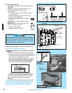
2. Mounting Safe-T-Beam
®
Source (Red LED) and
Sensor (Green LED).
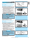
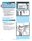
If garage has only one garage door.
– Determine which side of garage receives most
direct sunlight (Fig. 4-4).
– Red LED should always be on sunny side
whenever possible (Fig. 4-4).
For multiple doors.
– Preventing crossed signals is critical.
– Place source and sensor modules on adjacent
doors facing in opposite directions (Fig. 4-4)
.
NOTE: T
o help prevent interference from sun,
Safe-T-Beam
®
sensor with Green LED may be
placed further away from the door opening,
though extended no further out from the wall,
where it will spend more time in shadow.
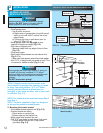
Slide source/sensor onto tongue of bracket until
it clicks into place (Fig. 4-3).
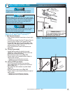
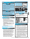
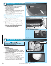
3a. Wiring (If NOT
pre-wired).
Route wire from Safe-T-Beam
®
to power
head using method shown in (Fig. 4-5a).
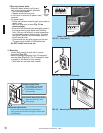
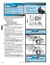
Securely fasten wires to wall and ceiling
as you go (Fig. 4-6 on next page).
– Use insulated staples.
– Staples should be snug only.
There should be no electrical power to the opener
while installing Safe-T-Beam
®
wires. If you have
plugged in the power cord—UNPLUG IT NOW!
WARNING
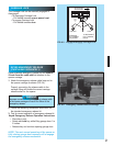
FIG. 4-1 Mark door frame
.
FIG. 4-2
Mounting brackets
.
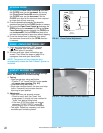
FIG. 4-3 Attach
Safe-T-Beam® to brackets
.
s
l
id
e
bracket
tongue
mark
center of
bracket
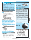
FIG. 4-4 Safe-T-Beam
®
source and sensor
locations
.
SUN
ONE DOOR
GARAGE
THREE DOOR
GARAGE
RED
LED
RED
LED
GREEN
LED
RED
LED
GREEN
LED
GREEN
LED
GREEN
LED
RED
LED
RED
LED
RED
LED
GREEN
LED
GREEN
LED
TWO DOOR
GARAGE
FIG. 4-5a Source and sensor wiring methods
.
or
6 5 4 3 2 1
6 5 4 3 2 1
SensorSource
neerGdeR
Power
Head
Dashed Line = striped wire
Solid Line = white wire
Insulated
Staple