


11
SR/SC Series "A" Woodburning Fireplace
7412948
NOTE: Safety strips are not required over noncom-
bustible floors where all supports at the base of the
fireplace are noncombustible.
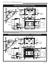
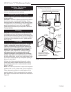
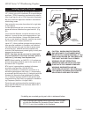
Four (4) nailing flanges are incorporated on each cor-
ner of the surround. Bend the nailing flanges out, level
the box, then secure it firmly in place by nailing the
flanges to the framing members as shown in Figure
15.
The following table gives firestop spacer model num-
bers:
Safety strips are used to ensure that any combustible
materials in front of the fireplace are protected even
though a noncombustible hearth extension is required.
If fireplace is to be elevated above the floor, a “Z”
shaped metal safety strip must be fabricated and used
to protect combustible surfaces in front of the fireplace.
This “Z” shaped safety strip is not provided but must be
fabricated of metal with each horizontal leg at least 1¹⁄₂"
(38mm) wide and equal in length to the metals strips
provided with the fireplace.
Installing Outside Air Kit
An outside air kit is installed in all SR/SC Series Fire-
places. If desired, or if local codes mandate the use of
an air kit, then an AK-MST is required to complete the
installation (from air kit to the outdoors). If the outside
air kit is to be used, the AK-MST MUST be installed BE-
FORE the fireplace is enclosed. Refer to the AK-MST
instructions for field installation.
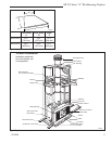
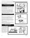
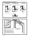
Installing the Chimney System
Start by attaching the first chimney section to the collar
on top of the fireplace.
Install the pipe as pictured in Figure 16. When you
get a good lock, you will hear the pipe clearly snap
together. Once sections are snap-locked in place, it is
extremely difficult to get them apart. Make sure the
pipe is firmly snapped and locked together as each
pipe section is mounted.
When installing elbows, only outer pipe will snap-
lock. Middle pipes simply slide into position. Be sure
to always attach straps on upper elbow to a structural
framing member. (Fig. 17)
The inside dimension of the frame must be the same
as the hole size selected from Figure 13 in order to
provide required the 1¹⁄₂" (38mm) of air space between
the outside diameter of the chimney and the edges of
the framed ceiling hole.
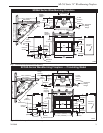
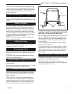
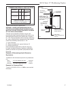
Positioning, Safety Strips,
Securing the Fireplace
Slide fireplace into position.
Lift the fireplace front slightly and slide the metal safety
strips under front bottom edge about 1¹⁄₂" (38mm), al-
lowing the remainder to extend in front of firebox. Over-
lap strips at least 1/2" (13mm) to provide a positive joint.
(Flat safety strips are packed with fireplace.) (Fig. 14)
FP557
BR
11/10/97
1"
FP557
Fig. 14 Safety strip installation.
1/2" Min.
Overlap
Metal Safety
Strips
(1, 2 or 3 pieces)
"Z" Safety
Strip
(not sup-
plied)
Fire-
place
Plat-
form
Hearth Ext.
FP549
Fig. 15 Fasten fireplace in position.
FP549
9/29/97
BR/BC
Nail Top
Standoffs
Nail Side-
Nailing
Flanges
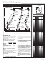
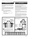
Fig. 13 Ceiling chimney hole sizes necessary for installing
firestop spacer.
Size of Chimney Vertical 30°
8" Flue SKFS2A SKFS6A
"SK" Series 14¹⁄₂" x 14¹⁄₂" 14¹⁄₂" x 25¹⁄₂"
(368mm x 368mm) (368mm x 648mm)
8" Flue FS2A FS6A
"S" Series 3-Wall 17¹⁄₂" x 17¹⁄₂" 17⁷⁄₈" x 29⁵⁄₈"
(445mm x 445mm) (454mm x 753mm)
Angle of Chimney at Ceiling