


39
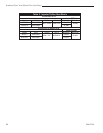
Stardance Direct Vent/Natural Vent Gas Heater
20012734
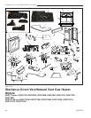
Remove Nuts
Remove Nut
Bottom View
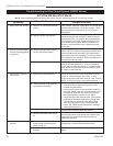
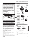
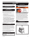
Fig. 71 Remove three (3) nuts securing ember bed in place.
ST918
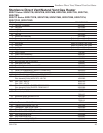
Pem Studs
ST919
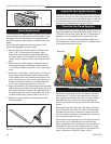
Fig. 72 Tilt ember bed slightly to correctly place on venturi
and air shutter.
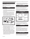
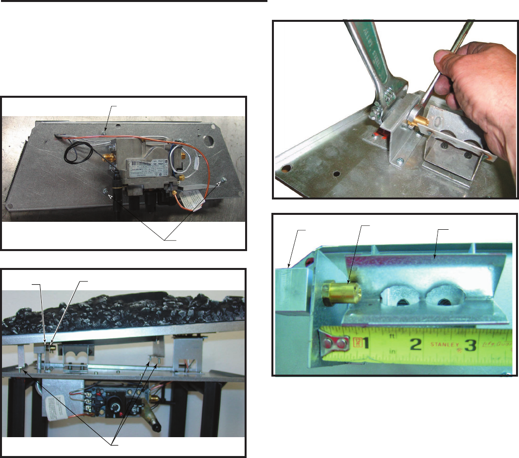
Orifice
Bracket
Venturi Bracket
Orifice
Bracket
Orifice
Air Shutter
CO142
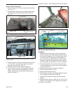
Fig. 74 The air shutter setting is 1/2” (13 mm) from the orifice
bracket to the edge of the air shutter.
Burner Orifice Conversion
1. Remove three (3) 3/8” nuts on bottom side of burner
pan. (Fig. 71)
2. Carefully remove ember bed by tilting the right side
up and lifting out toward the right side of the unit.
(Fig. 72)
All Models
1. Replace burner making sure venturi on bottom of
ember bed aligns with orifice and is seated properly
on air shutter assembly. (Fig. 72) Make sure burner
is slid into place at a slight angle and opposite to
how it was removed. When burner is slid into place,
the three (3) pem studs should slide down through
clearance holes into the bottom of the control panel.
2. Thread and tighten 3/8” nuts back onto pem studs
on underneath side of control panel, reversing Step
1 shown in Figure 71.
3. Reinstall logs as per instructions on Page 25.
4. Place conversion label on valve.
5. Replace glass and stove front.
6. Restore gas to system and relight appliance accord-
ing to Lighting Instructions on Page 30.
7. Leak check the system using a gas leak detector
solution.
8. Relight the main burner in both the “HI” and “LO” po-
sitions to verify proper burner ignition and operation.
Conversion is complete.
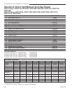
CO145
Fig. 73 Use two wrenches to avoid damage to manifold.
3. Remove injector orifice from left burner bracket with
a 1/2” wrench. Use a back up wrench to prevent
damage to the manifold. (Fig. 73)
4. Install conversion orifice. (Refer to Table 2)
5. The air shutter is factory set according to table on
Page 7 and should not need adjustment. The air
shutter opening may be verified by measuring as
shown in Figure 74.