


26
Stardance Direct Vent - Rear Vent Gas Heaters
20012950
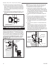
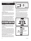
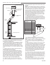
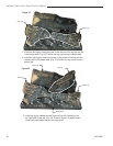
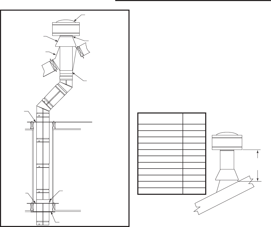
Vertical Termination
Approved Silicone
Sealant Here
Storm Collar
Flashing
Offset Support
Collar
Firestop
Spacer
Ceiling Support Collar
Ceiling
Support
Plate
Trim Plate
ST933
Fig. 46 Typical vertical venting configuration.
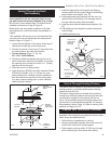
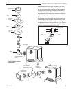
6. Install the ceiling support cathedral ceiling support
box assembly, as appropriate.
7. Determine the distance from the appliance outlet to
a point just above [approximately 12” (305 mm) to 24”
(610 mm)] either the cathedral ceiling support box or
the ceiling support plate and assemble lengths of pipe
to satisfy this distance. Do not attach assembly to appli-
ance.
8. Loosely position the support collar around the as-
sembled lengths (flared end down).
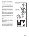
9. From above, lower the assembled pipe sections
down through the cathedral ceiling box or ceiling sup-
port plate and attach it to the appliance adapter. The
support collar should then be adjusted so that when
the assembled lengths of pipe are attached to the ap-
pliance, it rests on the bottom of the cathedral ceiling
support box on top of the ceiling support plate.
10. Tighten the tabs of the collar. Secure the sup-
port collar by inserting three (3) #8 x 1/4” sheet metal
screws through the support collar and the outer wall of
the pipe.
NOTE: If the cathedral ceiling support box assembly is
being used, it may be necessary to temporarily connect
the assembled pipe to the appliance. Determine and
mark the location of where the support collar will be at-
tached to the pipe. Disconnect and remove assembled
pipe. Attach the support collar per Step 10 (where
marked) and reinstall assembly. This is due to limited
space within the cathedral ceiling support box. Install
any required offset supports.
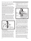
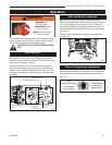
11. Add lengths of pipe and firestop as necessary
until assembly extends to a point above the roof which
complies with local code requirements for minimum ter-
mination height and with the appliance manufacturer’s
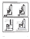
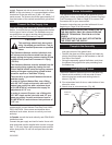
installation instructions. (Fig. 47)
Minimum Height
Above Roof
ST934
minimum height
6/07
Minimum
Roof Pitch Height
Flat to 7/12 1’0”
Over 7/12 to 8/12 1’6”
Over 8/12 to 8/12 2’0”
Over 9/12 to 10/12 2’6”
Over 10/12 to 11/12 3’3”
Over 11/12 to 12/12 4’0”
Over 12/12 to 14/12 5’0”
Over 14/12 to 16/12 6’0”
Over 16/12 to 18/12 7’0”
Over 18/12 to 20/12 7’6”
Over 20/12 to 21/12 8’0”
Fig. 47 Minimum Height Above Roof Requirements
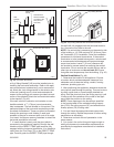
NOTE: Whenever DIRECT-TEMP penetrates through a
ceiling, a floor or a wall, it must be firestopped.
12. Using a level, make sure the system is perfectly
vertical.
13. Slide the flashing, suitable for the roof pitch, down
over the pipe protruding through the roof. Recheck
orientation and use a silicone sealant around and under
the perimeter of the flashing where it is in contact with
the roof. Secure the flashing with roofing nails. Finish
roofing around the pipe, covering the sides and upper
ares of the flashing base with roofing material. How-
ever, be sure the lower unnailed portion of the base
covers the roofing material.
14. Position the storm collar around the pipe and slide
down until it is in contact with the flashing. Secure the
storm collar by inserting the two (2) tabs into the raised
slots and fold tabs back. Seal the area between the
storm collar and the vent pipe with a silicone sealant to
prevent rain infiltration.
15. Install the vertical termination (VC) by inserting it
down into the top most section of pipe until it is fully