


11
Vermont Castings Radiance
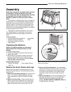
5. Resecure the Rear Shroud panels.
• Reinstall and tighten the two sheet metal screws
(D, Fig. 10) that secure the inner and outer shrouds
together.
• Secure the upper corner of the shroud and switch
box to the side of the stove using a 1/4 -20 x 1/2” round
head phillips screw, previously removed. (B, Fig.10)
Finally, replace the lower screw.
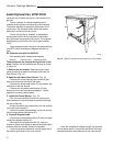
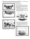
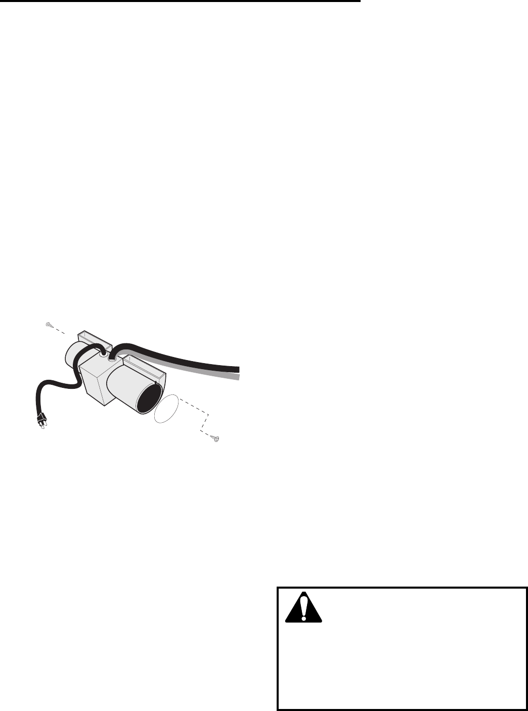
6. Attach the fan assembly to the bracket removed
earlier. Remove the sheet metal screws that secure the
finger guards at each end of the fan housing. Use these
screws to attach the fan to the bracket. (Fig. 12)
• Position the fan assembly so that the ducts slide
between the inner and outer shroud. The inner shroud
should engage with the two slots in the ends of the
bracket so that bracket and shroud are interlocked.
(Fig.14) Secure the bracket with the four sheet metal
screws previously removed.
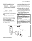
WARNING
The optional fan kit is equipped with a three-
prong (grounding) plug for your protection against
shock hazard and should be plugged directly into
a properly grounded three-prong outlet. Do not
cut or remove the grounding prong from this
plug.
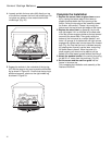
7. Install snapstat. (Fig. 13) Looking through the
stove front, locate the snapstat mounting screws on the
side of the left air duct under the top plate. Remove the
front screw (A), but only loosen the rear screw. Slip the
snapstat under the rear screw, replace the front screw,
and tighten both.
• Detach the extension wire from the retainer clip at
the rear. Connect the female flag connectors (B) of the
snapstat extension to the snapstat module. Confirm
that the wires are running to the back and away from
the top of the stove.
8. Plug the power cord into a standard grounded 110-
volt household outlet. If the fan control knob is not turned
to the OFF position, the fan will turn on when the tem-
perature at the snapstat reaches approximately 109°F.