


21
NVC Series B-Vent
20000194
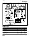
Optional Accessories
Fan Kits
FK12 Fan Assembly
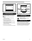
1. Open louvre assembly bottom.
2. Install FK12 fan in back of unit between hearth
supports.
3. Secure fan on velcro strips.
4. Power to the fan can be supplied by plugging the
supply lead into a conveniently located wall socket
or by using a hard-wired EB-1 connector box.
5. Be sure fan motor does not touch nearby metal.
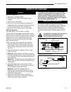
FK24 Fan Assembly
Fan specifications: 120 volt, 60 Hz, .75 Amps
This fan does not need regular maintenance, however
periodic cleaning is required. Check the area under the
control door and in front of the fan and wipe or vacuum
at least once a month during the operating season.
Should this fan require servicing, the power supply
must be disconnected.
The FK-24 comes with the electrical cord attached.
1. Slide fan assembly from the left side into the fire-
place opening, line up mounting holes with screw
studs on back of fireplace and fasten with #10-24
hex nuts.
2. Install thermal sensor on bottom of firebox using
#10-24 hex nuts.
3. (Option A) - Place electronic fan speed control box
on bottom of fireplace base, lining up mounting holes
with screw studs. Fasten fan speed control box with
#10-24 hex nuts.
(Option B) - The speed control can be installed in an
electrical box at normal wall switch height for conve-
nient access.
4. The power supply may be connected in 2 ways:
Method A - route the 6' (1.8m) lead fitted to the unit
to a conveniently located wall socket.
Method B - If the EB-1 receptacle box (Pt.
#ZA1200) was correctly connected when the unit
was installed, the fan lead can be directly plugged
into the EB-1 plug socket.
5. Whether wiring directly to the fan junction box,
(Option A) or into the EB-1 (Option B), first ensure
cable is secured using box connector.
The fireplace, when installed must be electrically
connected and grounded in accordance with local
codes or, in the absence of local codes, with the
current CSA C22.1 Canadian Electrical Code or for
US installations, follow local codes and the National
Electrical Code, ANSI/NFPA No. 70.
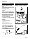
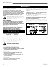
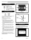
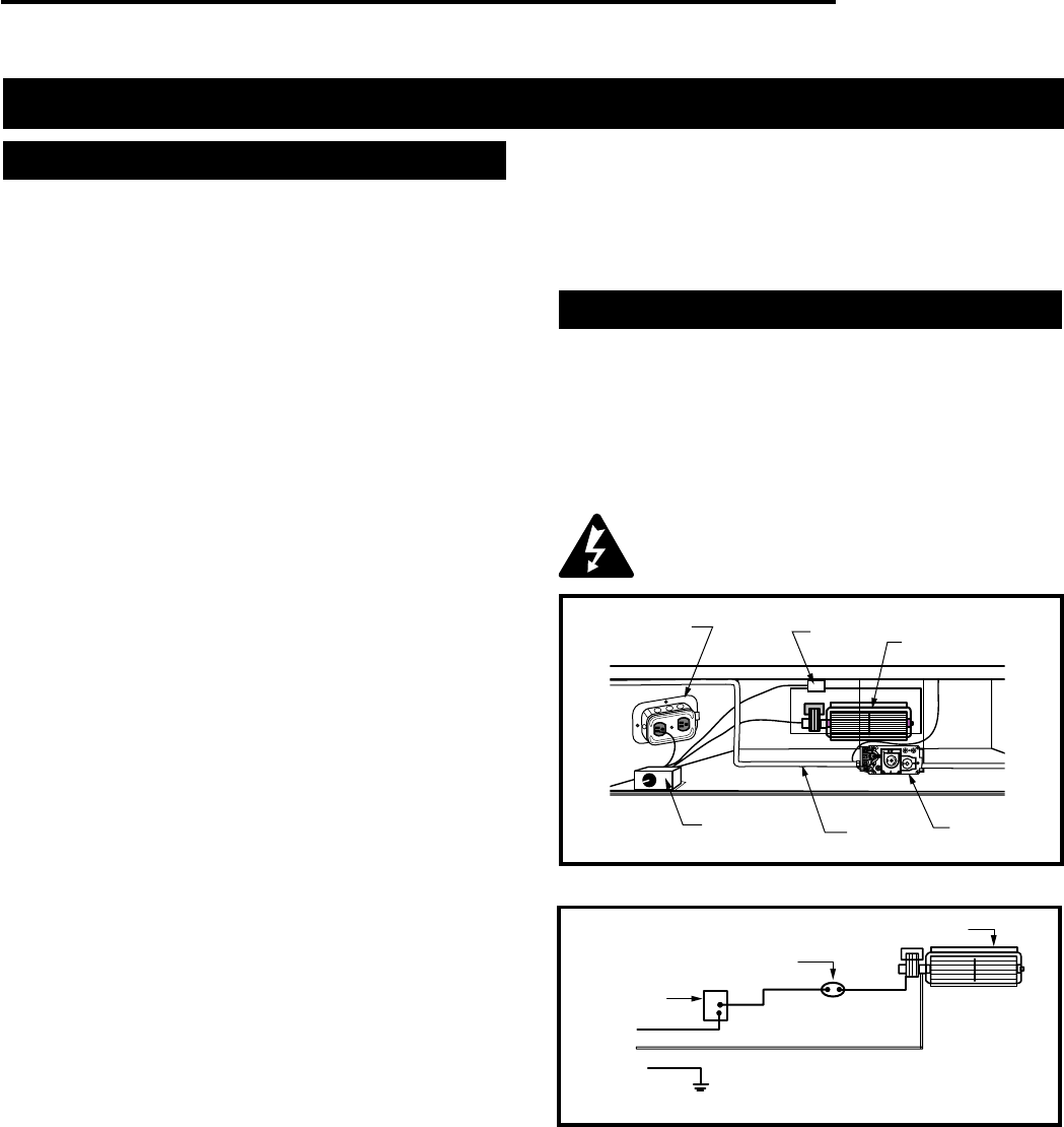
Hard (Direct) Wire Hook-Up
First connect the ground wire to the ground stud located
on the base of either box. Black wire from supply
should connect to the variable speed switch. Alternate
speed switch wire connects to temperature sensor.
Alternate lead from sensor connects to fan. Alternate
fan lead connects back to the white supply wire. (Fig.
23)
Any electrical rewiring of this fan must be
completed by a qualified electrician.
Turn off all power before hook-up.
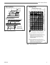
H
I
L
O
O
F
F
O
N
O
F
F
P
I
L
O
T
O
F
F
E
A
P
I
L
O
T
T
P
T
H
Electrical Box
Heat
Sensor
Fan
Valve
Gas Line
Fan Speed
Switch
FP1026
Fig. 22 FK-24 fan placement.
Black
White
Ground
Temperature
Sensor
Speed
Control
Fan
FP1025
Fig. 23 FK-24 fan wiring.