


11
NVC Series B-Vent
20000194
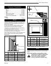
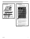
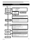
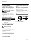
5. Place the front right log on top of the burner, Use
bottom holes to locate the logs on top of the studs.
6. Place the top logs onto the locator notches.
Ensure
that the logs a
re secure. (Fig. 12)
7. Place ember material. See "Ember Material Place-
ment" section.
NVC36 NVC39 NVC43
Front Left Log BB6 BC5 BD6
Front Right Log BB7 BC6 BD7
Rear Log BE5 BC7 BD8
Top Left Log BB9 BC8 BD9
Top Right Log BB10 BC9 BD10
Lava Rock
The lava rock provided with this fireplace must be
placed on the firebox base on either side of the burner
assembly. Do not place lava rock in combustion pan.
Under no circumstances should this lava
rock be placed on any part of the burner
assembly.
Ember Material Placement
Separate the ember material into small pieces, roughly
1/2" in diameter, and place onto the burner in front of
the front logs. Do NOT pack down, leave in fluffy, loose
condition for more realistic ember effect.
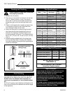
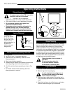
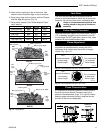
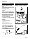
Flame Adjustment
For fireplaces equipped with HI/LO valves, flame
adjustment is accomplished by rotating the HI/LO
adjustment knob located near the center fo the gas
control. (Fig. 13 or 14)
LO
HI
Turn
counterclockwise
to decrease
flame height
Turn clockwise
to increase
flame height
Fig. 13 Flame adjustment knob for Honeywell valve.
HV102
Turn
counterclockwise
to increase
flame height
Turn clockwise
to decrease
flame height
I
H
LO
Fig. 14 Flame adjustment knob for SIT valve.
HV116
Fig. 12 Log locations.
BE5 Log Rear
BB9 Log Top Left
BB10 Log Top Right
BB6
Log Front
Left
BB7
Log
Front
Rigth
NVC36
BD8 Log Rear
BD9 Log Top Left
BD10 Log Top Right
BD6
Log Front
Left
BD7
Log
Front
Right
NVC43
BC7
Log
Rear
BC8 Log Top Left
BC9
Log Top Right
BC5 Log
Front
Left
BC6
Log Front
Right
NVC39
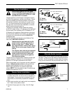
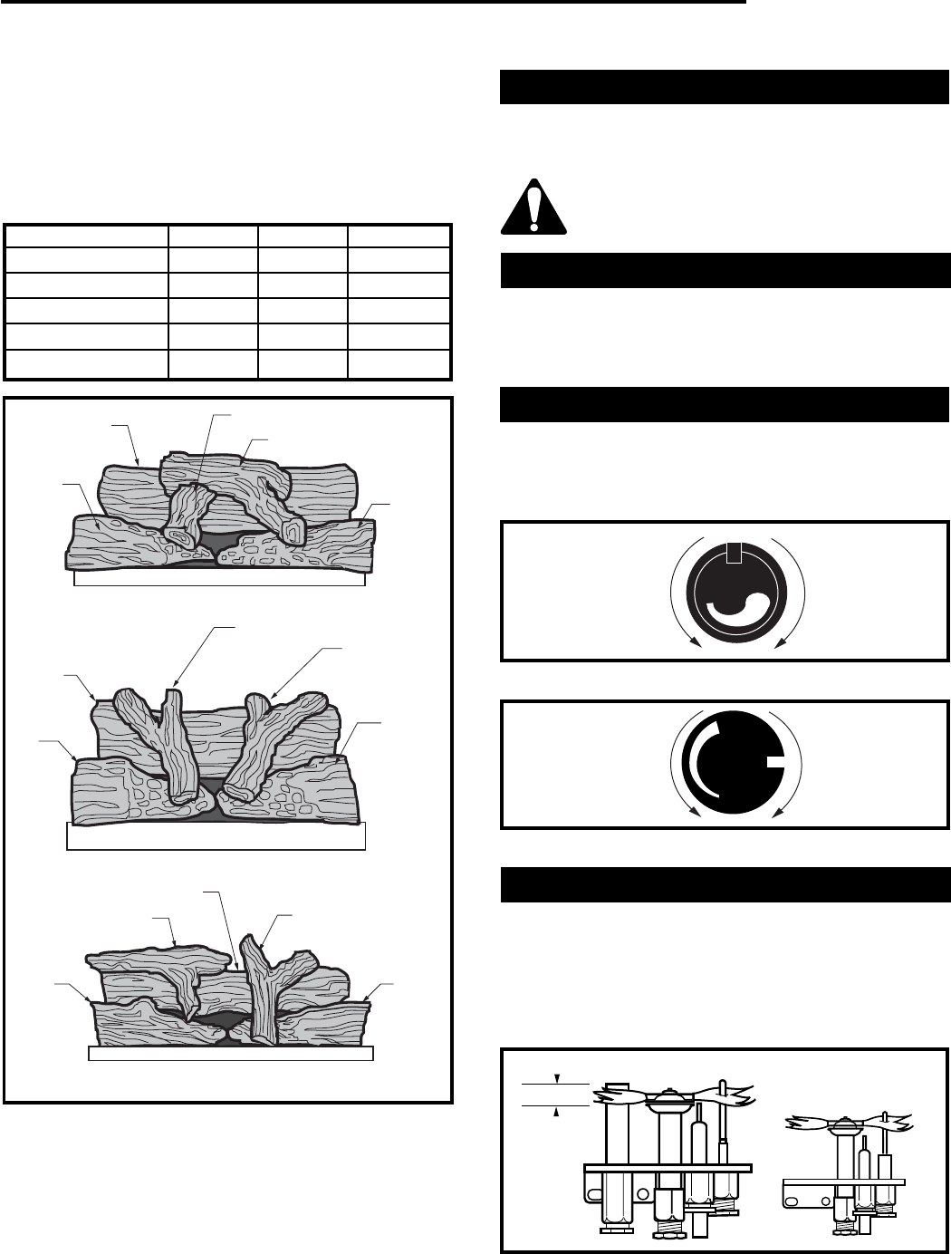
Flame Characteristics
It is important to periodically perform a visual check of
the pilot and burner flames. Compare them to the ,
pictorials illustrated below. (Figs. 15 or 16) If the flame
patterns appear abnormal contact a qualified service
provider for service and adjustment.
Fig. 15 Proper pilot flame height.
FP392/585
3/8"-1/2"
Electronic
Ignition