


11
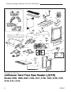
Vermont Castings Jefferson Vent Free Gas Heater
20003447
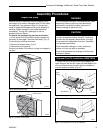
Decorative Grate
ST223
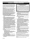
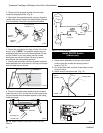
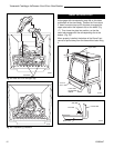
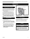
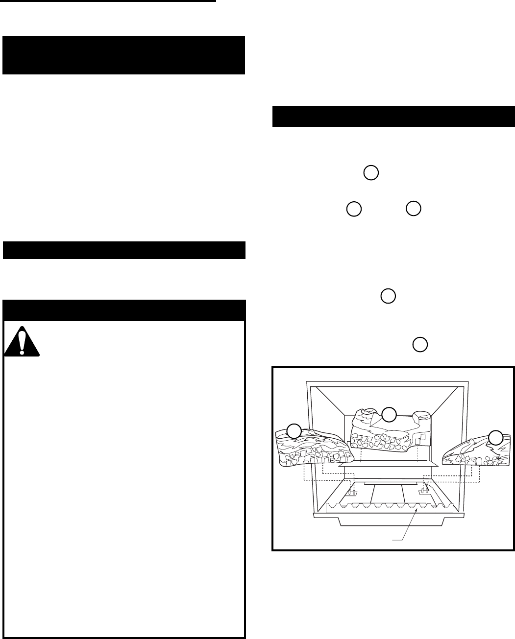
Fig. 14 Install back, left and right logs.
1
2
3
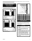
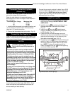
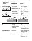
Thermostat Wire / Gauge Maximum Run
18 40 feet
20 25 feet
22 16 feet
Thermostat Connection (optional)
(R Models only)
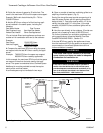
1. Install the wall thermostat in the desired location and
run the wires to the stove location. Terminate these
leads with 1/4” female connectors.
2. Connect the thermostat wires to the valve. (Fig. 13)
Use only a thermostat rated for 500 millivolts. Do
not use low voltage (24V) thermostats.
Check the table below for the appropriate gauge
thermostat wire to use for the length of lead required in
your installation.
4
5
1
3
2
Install the Log Set
1. Remove the logs from their packaging, and inspect
each piece for damage. DO NOT INSTALL DAM-
AGED LOGS.
2. Install the rear log by centering it side to side on
the sheet metal shelf at the back of the firebox.
(Fig. 14)
3. Install the left and right middle logs by
engaging holes on their bottoms with pins on the
burner brackets. (Fig. 14)
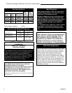
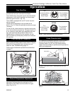
4. Loosely sprinkle the small package lava rocks
directly on top of the burner between the decorative
grate and the middle logs. Do not place any lava
rocks behind the middle logs. (Fig. 15)
5. Engage the upper log with the right middle log as
shown in Figure 15. Swing the top end toward the
rear of the firebox and rest on notch on top of rear
log. (NOTE: This log will touch the back of the
firebox.) Engage the top log with the upper log
and the left middle log. (Fig. 15)
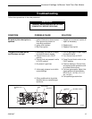
Connect the Gas Supply Line
Check the Rating Plate attached by a steel cable to the
firebox, to confirm that you have the appropriate firebox
for the type of fuel to be used.
This appliance should only be con-
nected by a qualified gas technician.
Test to confirm manifold pressures as
specified below.
The Jefferson Heater and its individual shutoff
valve must be disconnected from the gas supply
piping during any pressure testing of that system
at test pressures in excess of 1/2 psig (3.5 kPa).
The Jefferson Heater must be isolated from the
gas supply piping system by closing its individual
manual shutoff valve during any pressure testing
of the gas supply piping system at test pressure
equal to or less than 1/2 psig.
There must be a gas shutoff between the stove
and the supply.
In order to connect Natural Gas, use a fitting with
3/8” NPT nipple on the valve side and 1/2” natural
gas supply line with an input of 28,000 BTUs at a
manifold pressure of 3.5” and minimum inlet
supply for adjustment of 5.5” W.C.
In order to connect Propane, use a fitting with 3/8”
NPT nipple on the valve side and 1/2” propane
gas supply line with an input of 28,000 BTUs at a
manifold pressure of 11.0” and minimum inlet
supply for adjustment of 11.0” W.C.
CAUTION
Gas connection should be made in accordance with
current National Fuel Gas Code, ANSI Z223.1. Since
some municipalities have additional local codes, be
sure to consult you local authority.
Connect the gas supply and test for leaks. Use a 50/50
solution of liquid soap and water to test for leaks at gas
fittings and joints.
NEVER test with an open flame.
Light the pilot according to the directions on page 14,
before going to the next step.