


1010
Vermont Castings Jefferson Vent Free Gas Heater
20003447
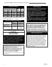
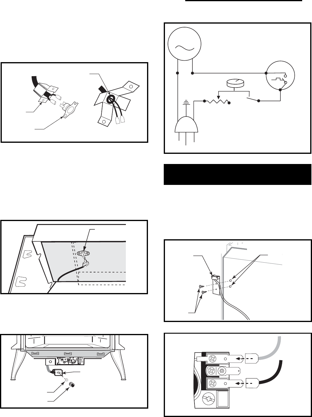
MOTOR
SNAPSTAT
ON/OFF
RHEOSTAT
WHT
WHT
BLK
BLK
BLK
GRN
BLK
ST236
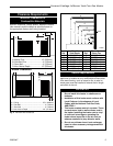
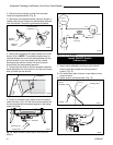
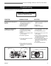
Fig. 11 Fan wiring diagram.
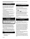
ST347a
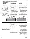
Fig. 10 Attach rheostat to control panel. Valve may look
different.
Rheostat
Retaining Nut
Control Knob
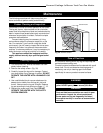
Pinch Grommet
to Remove
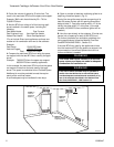
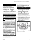
Snapstat
Bracket
Snapstat
Module
ST468
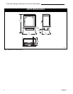
Fig. 8 Remove snaptstat and grommet from bracket.
2. Disconnect the snapstat module from the leads
inside the snapstat bracket. (Fig. 8)
3. Bend open the snapstat bracket. use your fingers or
needle nose pliers to remove the black plastic grommet
from the bracket. Discard the grommet and bracket.
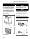
4. Secure the snapstat to the upper middle of the inner
shroud. (Fig. 9) NOTE: The snapstat location may be
reached through the front of the stove between the top
and the firebox or you may loosen the four screws
holding the rear shroud in place. Be sure to secure
shroud back into place before operation.
5. Connect the two wires to the two snapstat extension
leads attached to the inner shroud. You may coil excess
wire up inside the rear shroud.
6. Route the rheostat control switch and wire forward
under the stove. (Fig. 10) Use the wire tie to secure the
fan and rheostat wire harnesses together to the tubing
under the heater.
ST346a
Fig. 9 Attach snapstat to inner shroud.
Snapstat
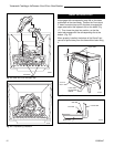
Install ON/OFF Switch
(R Models only)
The switch assembly parts are found in the parts bag.
1. Attach switch assembly to left rear side of stove
shroud using two screws and existing holes in
shroud. (Fig. 12)
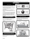
2. Run wires down back of stove, under bottom of rear
shroud to valve.
3. Attach wires to valve terminals. (Fig. 13)
TP
TH
TPTH
ST228
Fig. 13 Attach switch wires to valve.
Existing Holes
Switch
Assembly
Screws
ST315
Fig. 12 Attach switch assembly to rear shroud.