


24
Irving Oil
10004000
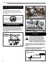
FAN
Antenna
Red
White
Red
White
Pilot Assembly
Valve
(Bottom View)
Fan
Delay Timer Mode
The shut off delay timer has a maximum of 2 hours and
a minimum of zero minutes. To change the timer level,
press the time key followed by an arrow key. Pushing
the key once will change the timer by 10 minutes.
Auto Mode
In the AUTO mode, the room temperature, set tem-
perature, flame and fan levels will be shown. AUTO will
appear next to both the flame and fan icons.
When the control is in the AUTO mode, the main
burner will turn on/off or modulate based on the heat
needed to maintain the set temperature. The flame
level will change automatically to optimize the heat
output needed to maintain the set temperature. To
change the set temperature, press the up or down key.
Pushing a key once will change the temperature by
one degree.
In the AUTO mode, the fan speed will increase with
increasing flame height or decrease with decreasing
flame height. “AUTO” is displayed next to the flame and
fan icons.
Fan Override During Auto Mode
If a lower or higher fan speed is desired when operat-
ing in the AUTO mode, the fan speed can be overrid-
den by pushing the fan button followed by the up or
down key. Pushing a key once will change the fan level
by one unit. In this mode “AUTO” is displayed next to
the flame icon and “MANUAL” is displayed next to the
fan icon.
Change Between F/C Temperature Units
Push the up and down arrow keys simultaneously for at
least 3 seconds to toggle between Fahrenheit and
Celsius units.
Disable Thermostat Function
To disable the thermostat function in the AUTO mode,
push the time and down keys simultaneously for at
least 3 seconds.
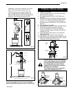
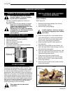
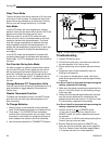
To Change Batteries
1. Remove cover on the backside of the transmitter.
Install 3 AAA batteries as shown and reattach cover.
2. Once steps 1-3 in OPERATION are completed,
receiver/valve and transmitter are now ready. Press
any button on transmitter for recognition process to
occur between the receiver/valve and transmitter.
3. Use functions as described in TRANSMITTER section.
Troubleshooting
1. Locate LED light on valve.
2. LED will blink after every valid command received
by the transmitter; this is not an error.
3. Failure codes may occur anytime after pilot burner
is lit.
4. Sequence is failure code followed by light not
blinking for 30 seconds.
5. In the event of multiple failure codes, next failure
code follows previous failure code by approximately
3 seconds.
If an Error Code 3 is observed while performing the
testing, complete the following:
1. Make sure the spade connectors are pushed all the
way on. If rhe Error Code 3 is still showing, then go
to the next step.
2. Switch the front two thermopile leads with the back
two. Be sure the white lead is connected to the
spade with the white dot next to it. If the Error Code
3 is still showing, replace the thermopiles.
If an Error Code 8 is observed while performing the
testing, complete the following:
1. Confirm the valve is not in REMOTE mode.
• If the valve is producing Error Code 8 and in
REMOTE mode, the valve is defective and should
be replaced.
• If the valve is in LOCAL mode and producing Error
Code 8, then go to the next step.
2. Slide the Remote/Local switch to REMOTE and
teach the valve a transmitter (see item 6, page 23).
The Error Code will clear itself after approximately
1.5 minutes and return to normal operation.
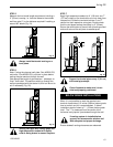
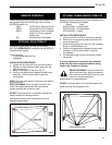
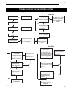
Fig. 41 Comfort Valve wiring diagram.