


20
Irving Oil
10004000
RN/RP Models
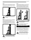
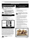
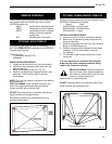
For units equipped with ‘HI/LO’ valves the flame
adjustment is accomplished by rotating the ‘HI/LO’
knob located near the center of the gas control valve
(See Fig. below).
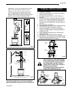
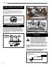
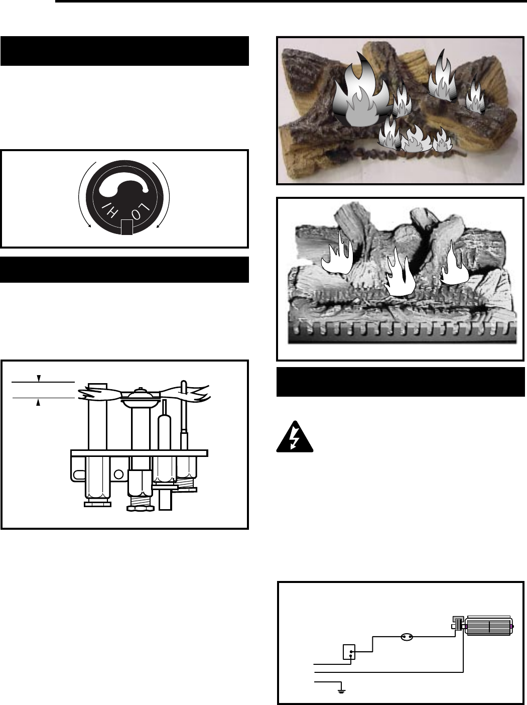
It is important to periodically perform a visual
check of the pilot and burner flames. Compare
them to the pictorials illustrated below (Fig. 34, 35,
& 36). If any of the flames appear abnormal call a
service person.
FLAME CHARACTERISTICS
FLAME & TEMPERATURE ADJUSTMENT
IRFSDV34
Fig. 36
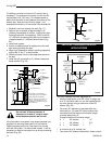
Turn
counterclockwise
to decrease
flame height
Turn clockwise
to increase
flame height
Honeywell Valve
Fig. 34
3/8" - 1/2"
IRFSDV24
Fig. 35
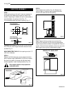
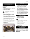
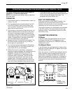
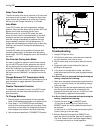
FAN - FK24
This fan assembly comes completely
wired to eliminate the need for elec-
tricians. This electrical device must be
electrically connected and grounded in
accordance with local codes. In the
absence of local codes, with the current
CSA C22.1 CANADIAN ELECTRICAL CODE.
For USA installation: Follow local codes and the
NATIONAL ELECTRICAL CODE ANSI/NFPA No.
70-1984.
Should this fan require servicing, the power supply
must be disconnected. For rewiring of any
replacement components see Fig. below.
C
B
A
Black
White
Ground
A: SPEED CONTROL
B: TEMPERATURE SENSOR
C: FAN