


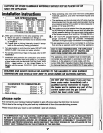

temperature
range
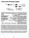
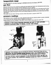
The thermostat
(#1
see berow
drawing)
is
caribrated
and
set
at
the
factory'
(55-110"F)
gas
flow
Maximum
flow
rate
can
be
checked
by
cooling
the
thermostat
bulb
below
room
temperature
and
turning
the
knob
(#4 see
below
drawing)
counter
clockwise
to
the
Hl
position'
Minimum
flow
rate
can
be checked
by
cooling
the
thermostatic
bulb
below
room
temperature
and
turning
the
knob
(#4 see
berow
drawing)
counter
crockwise
$;rt
"no
rtopping
when
you hear
the
"snap"'
This
flow
rate
is
determined
by
the
o.E.M.
at
the
design
rt"i"
and
seiwitfr
a
pre-drilled
screw
(minimum
rate
screw).
This
screw
(#3
see
below
drawing)
must
be
driven
fully
down
to
assure
proper
flow'
pressure
readings
tnret
pressure
can
be
checked
by
turning
captured
screw
(#6 see
drawing
below)
counter
clockwise
2 or
3
turns
and
then
placing tubing
to
gauge
over
test
point'
Oulet
pressure can
be checled
in
[he
same
manner
above
using
captured
screw
(#7)'
WARN'NG;
AFTER
TAKING
PRESSURE
READINGS,
BE
SURE_I9JIJRN
CAPTURED
SCREWs
cLOcKwGi
rrnnrLY
TO
RESEAL.
DO
NOT
OVER
ToROUE'
WARN'NG;
THE
CONTROL
HAS
AN
INTERLOCK
DEVICE;
AFTER
SHUTTING
OFF
ALL
cAs
FLow,
rHE
ptLor
BURNER
crnHor
BE
RELri
rli,r^::t^ Tlt^T*t:3:::i
to'
8ffi
H,i
r'rt=*ii
"'*'
i,il
E
HH;
iil\c
N
Ei
io
e e
n
e
''
r
s
e
D
(
a
p
p
rox.
:
t-
.:::' I .
THE
GAS
CONTROL
KNOB
IS
DESIGNED
TO
BE-OPERATED
BY
HAND'
DO
ilOT
USE
ANy
rooLs
DURTNG
rHrs
opERAiiNG.
DAMAG'6-ftrloes
MAY
RESULT
lN
sERlous
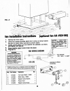
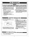
Pilot
Adiushent
Screw
Minimun
Rate Screw
Pressure
Regulalor
i
0ullel
Pressure
Test
Pornt
lnlel
Plessure
Iesl
Poinl
Iemperalure
Sensing
Bulb