


17
Encore Woodburning Stove
2000956
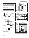
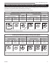
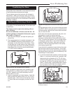
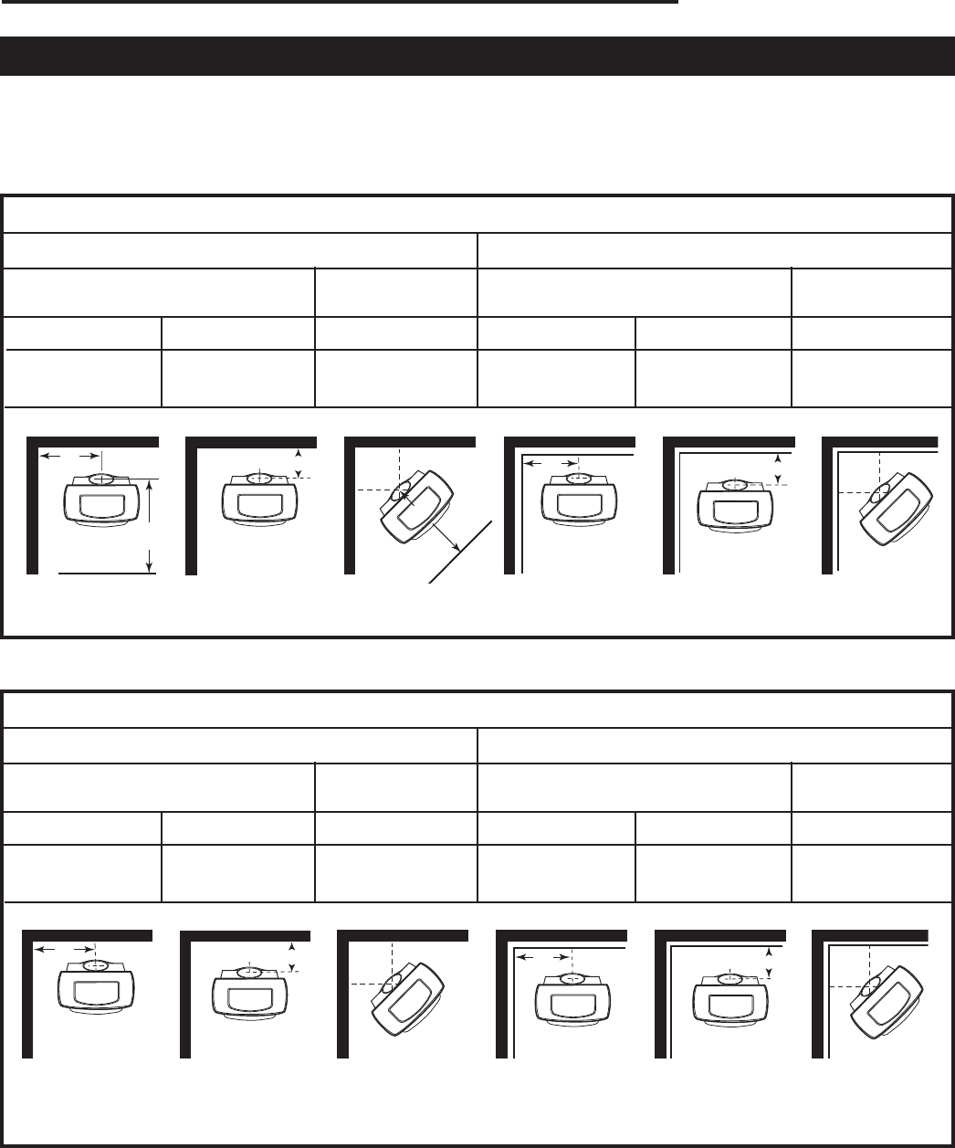
Distance from the Center of the Flue Collar to the Wall in Top-Exit Installations
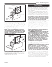
The information on this page is helpful in planning stove placement for top-exiting installations, particularly those in-
stallations with chimneys that pass through the ceiling. However, this is not a clearance chart. Final stove clearances
must adhere to the guidelines stated in the clearance chart on Page 14.
Dimensions indicated are valid for installations with either 6” or 8” flue collars.
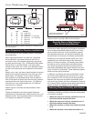
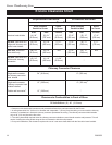
Encore: WITH Stove and Chimney Connector Heat Shields
Unprotected Surfaces Protected Surfaces
Corner Corner
Parallel Installations Installations** Parallel Installations Installations**
Side (A) Rear (B) Corner (C) Side (A) Rear (B) Corner (C)
37
¹⁄₂” 15³⁄₄” 24” 21¹⁄₂” 7³⁄₄” 14”
(953 mm) (400 mm) (610 mm) (546 mm) (197 mm) (356 mm)
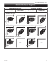
**To locate center of flue collar for corner installation, add 7” (180mm) to the clearance distance from stove corner to wall. Mark
off the resulting distance from the corner along both walls. Next, measure the same distance from these two points out from the
walls. These last two measurements will meet at a point representing the center of the flue collar. Refer to the diagrams above.
ST632a
ST632a
Encore
flue centerline
Diagrams
02/01
A
B
C
D
E
F
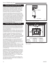
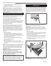
Encore: WITHOUT Stove and Chimney Connector Heat Shields
Unprotected Surfaces Protected Surfaces
Corner Corner
Parallel Installations Installations** Parallel Installations Installations**
Side (A) Rear (B) Corner (C) Side (A) Rear (B) Corner (C)
37
¹⁄₂” 27³⁄₄” 31” 21¹⁄₂” 11³⁄₄” 15”
(953 mm) (705 mm) (787 mm) (546 mm) (299 mm) (381 mm)
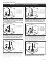
* This distance, from the center of the flue collar to the front edge of the hearth, is the same for all installations on this page:
35” in the United States and 37” (940mm) in Canada.
ST632
ST632
Encore
flue centerline
Diagrams
2/01
*
A
B
C
*
D
E
F