


14
Encore Woodburning Stove
2000956
24” (610 mm) 8” (203 mm)
12” (305 mm) 4” (102 mm)
2
12” (305 mm) *
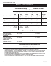
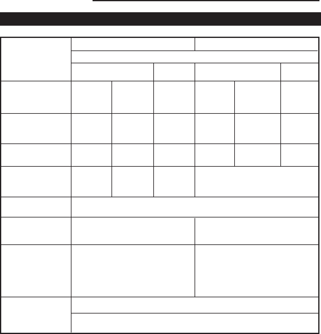
(A) 24” (B) 31” (C) 24” (D) 8” (E) 15” (F) 8”
(610 mm) (787 mm) (610 mm) (203 mm) (380 mm) (203 mm)
(G) 24” (H) 19” (I) 17” (J) 8” (K) 11” (L) 7”
(610 mm) (483 mm) (432 mm) (203 mm) (280 mm) (178 mm)
(M) 24” (N) 19” N/A (P) 8” (Q) 11” N/A
(610 mm) (483 mm) (203 mm) (280 mm)
(G) 24” (H) 19” (I) 24”
(610 mm) (483 mm) (610 mm) *
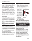
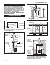
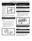
Stove Clearance
Unprotected Surfaces Protected Surfaces
Chimney Connector Clearance
Single-wall connector,
No chimney connector
heat shields
Single-wall connector,
Chimney connector heat
shields installed
Double-wall connector
3
Clearance to Combustibles in Front of Stove
All Installations (S) 48” (1219 mm)
* Clearances with double-wall connectors and protected surfaces have not been tested for the Encore.
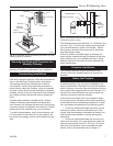
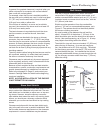
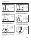
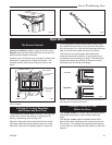
1. A ceiling heat shield, 24” (610 mm) in diameter and suspended 1” (25 mm) from the ceiling, must surround the chimney
connector in installations in which the chimney connector penetrates the ceiling. The chimney connector shield extends
only to 28” (710 mm) above the flue collar.
2. The ceiling heat shield required when the chimney connector shields are used should meet the wall protector. This will
require trimming the ceiling shield along the line of intersection with the wall protector.
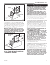
3. In top-exit installations, this clearance requires the use of a rear stove heat shield with the flue collar insert installed.
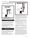
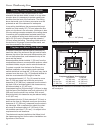
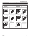
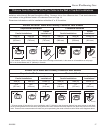
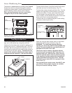
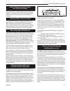
Encore Clearance Chart
For use with either 6” or 8” flue collar/chimney connection
Stove Installed Stove Stove Installed Stove
Parallel to Corner in Corner Parallel to Wall in Corner
Side Rear Corners Side Rear Corners
No stove heat shields
Top Exit, rear stove h.s.,
single-wall chimney con-
nector heat shields
1
Rear Exit, rear stove
heat shield only
Top Exit, rear stove h.s.,
double-wall chimney
connector
3