26
Chateau™
20011956
LG406
Upper logs
3/05
Log Rear Upper
Middle (DVT44 Only)
Log Front
Upper Right
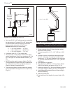
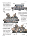
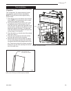
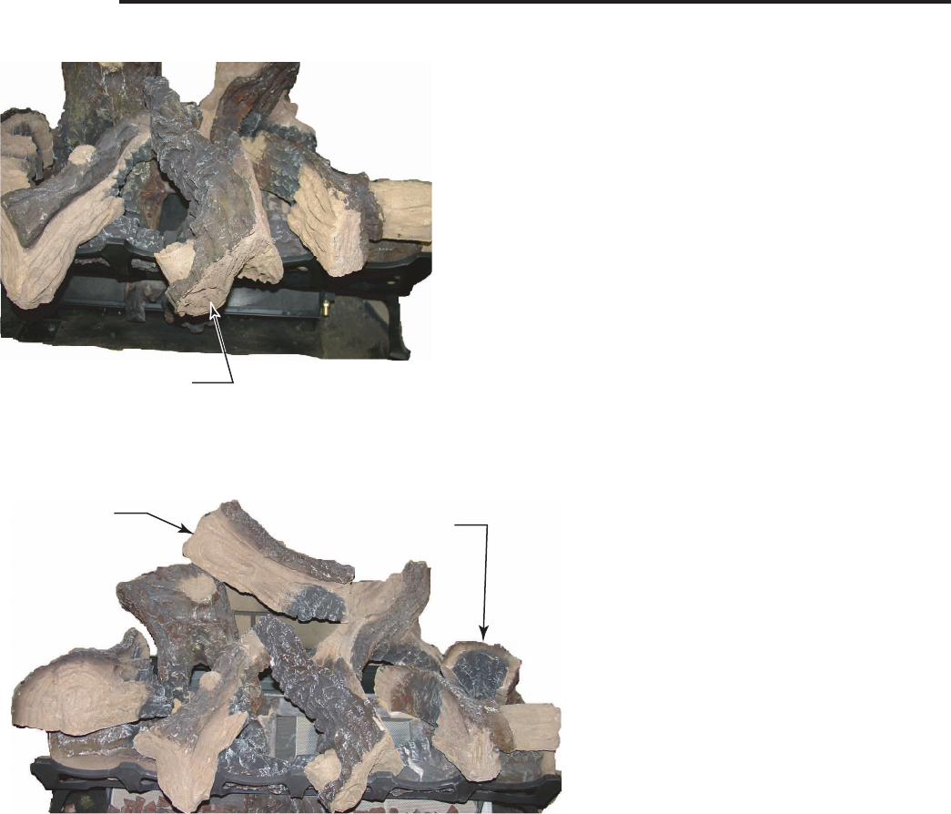
Figure 47
LG406
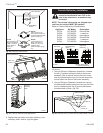
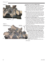
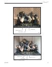
12. Position the Log Front Middle Right.
DVT38 only.
Hold the log with the pointed end toward
the back and the wide end toward the front. Set the
rectangular indentation located on the bottom of
this log over the third right tine on the grate. Lay the
pointed end of the log over the flat area located on
the pointed end of the front middle log. (Fig. 46)
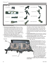
DVT44 only. Hold the log with the pointed end toward
the back and the wide end toward the front. Set the
V-shaped end on the front of this log (split area) on
the third right tine on the grate. Lay the pointed end
of the log over the flat area located on the pointed
end of the front middle log. (Fig. 45)
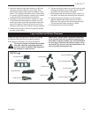
13. Position the Log Front Right. Hold the log with the
pointed end toward the back and Y-branch toward
the front. Set the rectangular indentation located on
the bottom over the rectangular protrusion located
on the right grate log. Lay the pointed end of the log
over the notched part of the overlay. When the log is
in place, the pointed end is located on the left of the
pilot assembly. (Fig. 45 )
14. Position the Log Front Upper Right. Hold the log
with notched end toward the front and the pointed end
toward the back. Set the notched end over the front
right log. Lay the pointed end over the manifold tube
located to the right of the burner housing. (Fig. 47)
15. DVT44 only. Position the Log Rear Upper
Middle. Hold the log with split detail toward the
front and the flat end toward the back. Set the
round indentation located on the bottom over
the round protrusion located on the rear left
log toward the back. Set the right end of the
log on the split end located on the right rear
log toward the left. When this log is in place, it
sets side to side. (Fig. 47)
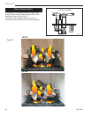
NOTE: Refer to Figures 48 and 49 for com-
plete logset.
LG407
DVT38
front middle log
3/05
Log Front
Middle (DVT38)
LG407
Figure 46


