


10
Chateau™ Direct Vent Gas Fireplace
20011957
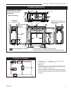
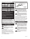
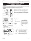
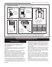
19.If you choose to install the optional wireless wall
mounted remote control (Part No. 20012267), install
two (2) button batteries provided with the remote
control by removing four (4) screws holding the back
cover in place. Carefully remove the circuit board.
Install batteries with dimpled side showing. (Fig.
9) Carefully replace circuit board and back cover.
Tighten screws.
FP1824
wall transmitter batteries
11/07
Install two (2)
Batteries with
Dimpled Side
Showing
FP1824
Fig. 9 Inside view of wireless wall switch.
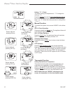
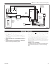
20.Locate the learn button on the main module. (Fig.
8) Press and release the learn button using a pencil
point. There will be a beep sound from the module.
Then press any key on the hand-held remote control
transmitter. Once the module’s internal receiver ac-
cepts the transmitter code, there will be a series of
confirming beeps. If you are using the optional wall
mountable remote control transmitter, press the learn
button on the main module a 2nd time. There will be
a beep sound from the module. Then press the ON
button on the wall mountable transmitter. Once the
module’s internal receiver accepts the transmitter
code, there will be a series of confirming beeps.
21.The fireplace remote system is now ready for use
and will respond to either wireless transmitter.
22.Reassemble access panel, burner assembly, gas
supply connector, brick panels, logs, embers, and
-
irons and lava rock in reverse order of removal. (Re-
fer to Log, Lava Rock and Ember Placement section.
23.Turn on gas supply and check that all connections
are tight and leak free.
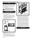
NOTE: If you need to test the inlet pressure and/or
manifold pressure, there are two (2) test ports available
along the right side front edge between the firebox side
and outer casing. The upper test port is inlet pressure.
The lower test port is manifold pressure. (Refer to Fig-
ure 8)
CAUTION: Turn off the gas supply before
removing test port plug.
24.Using a 7/16” nut driver, remove the threaded plug
from the test port.
25.Thread the supplied extension adaptor into the open
test port.
26.Attach a 1/4” diameter pressure gauge flexible hose
fully onto the barb of the adaptor.
27.Turn on gas supply and operate valve with remote
control as needed to indicate gas pressure.
CAUTION: Turn off the fireplace and gas
supply before removing test port adaptor
and replacing plug.
28.After test, remove extension adaptor and replace
plug securely.
29.Turn on gas supply and check that plugs are tight
and leak free.
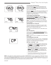
Special Feature for Cold Climates
This gas control system has the option of a continu-
ous pilot feature. This allows the user to change from
a spark to pilot system to a standing pilot system for
direct vent appliances during cold climate conditions to
keep the firebox warm.
When the continuous pilot mode is activated and the
fireplace is turned ON, the pilot will spark and light.
When the fireplace is turned OFF, the pilot will stay ON
when the main burner shuts OFF.
The continuous pilot mode can be activated or de-acti-
vated by the hand held remote control transmitter.