


- 26 -
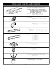
FAN KIT - FK24
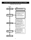
It will be easier to install the fan before
connecting the gas line to the fireplace.
1. Open front access door panel by pulling forward on
brass lip.
2. Install the fan through the opening at the back of the
pedestal, with the outlet pointed up and the fan mounting
bracket facing the back of the fireplace (Fig. 44). . The
fan mounts over two studs which hold the fan just below
the firebox floor. Hold the fan in place with the two nuts
provided.
3. Locate the fan speed control/junction box on screw
studs provided on base of the fireplace. Tighten with
nuts.
4. Install thermal sensor element on screw studs located
to the right of the gas valve on the burner base.
5. Plug in grounded service cord to a convenient wall
receptacle.
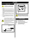
OPTIONS
REMOTE CONTROL
Only for units with RN/RP valve.
MRC1 - On/Off Button Remote Control
MRC2 - Temperature Control Remote
MRC3 - Temperature Control w/digital display &
24 hour programmable clock
IMT - Wall Mounted Thermostat
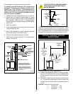
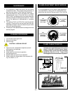
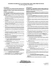
Fig. 43
TOP VIEW
Valve
Fan speed
control/
Junction
box
Thermal sensor
location
Fan is
installed at
the back
of the
pedestal
Stud
This fan assembly comes completely wired to
eliminate the need for electricians. This
electrical device, when installed, must be
electrically connected and grounded in
accordance with local codes. In the absence of
local codes, with the current CSA C22.1
CANADIAN ELECTRICAL CODE.
For U.S.A. installation: Follow local codes and
the NATIONAL ELECTRICAL CODE ANSI/
NFPA No.70-1984.
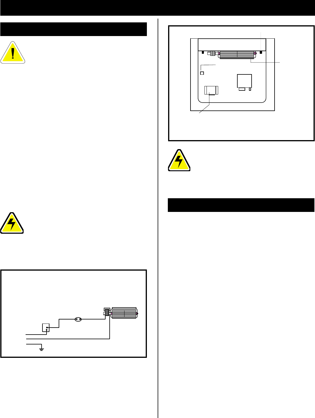
Fig. 44
C
B
A
Black
White
Ground
A: SPEED CONTROL
B: TEMPERATURE SENSOR
C: FAN
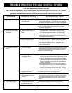
Should this fan require servicing, the power
supply must be disconnected. For rewiring
of any replacement components see Fig. 43.