


- 12 -
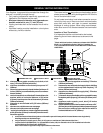
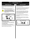
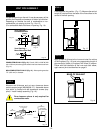
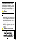
STEP 2
Measure wall thickness and cut zero clearance sleeve
parts to proper length (MAXIMUM 12"). Assemble sleeve
and attach to firestop with #8 sheetmetal screws (sup-
plied). Install firestop assembly (Fig. 16)..
Zero clearance sleeve is only required for
combustible walls.
#8
SCREWS(2)
ADJUSTABLE ZERO
CLEARANCE SLEEVE
ADJUSTABLE
ZERO CLEARANCE
SLEEVE
#8
SCREWS(2)
#8
SCREWS(2)
Maximum Length
12" (294mm)
FIRESTOP
Fig. 16
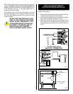
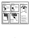
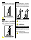
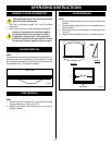
STEP 1
Locate vent opening on the wall. It may be necessary to first
position the fireplace and measure to obtain hole location.
Depending on whether the wall is combustible or non-
combustible, cut opening to size. Fig. 13 or 15.
(For combustible walls first frame in opening. Fig. 14).
(240mm)
9-
3/8
"
9-
3/8
"
(240mm)
7-
1/2
"
(190mm)
Vent Opening —
Combustible Wall
Vent Opening —
Noncombustible Wall
(framing detail)
Fig. 13
Fig. 15
VENT PIPE ASSEMBLY
Fig. 14
COMBUSTIBLE WALLS (Fig. 13): Cut a 9-3/8"H x 9-3/8"W (240
mm x 240 mm) hole through the exterior wall and frame as shown
(Fig. 14).
NON-COMBUSTIBLE WALLS (Fig. 14): Hole opening must be
7.5" (190 mm) in diameter.
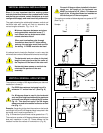
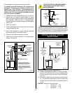
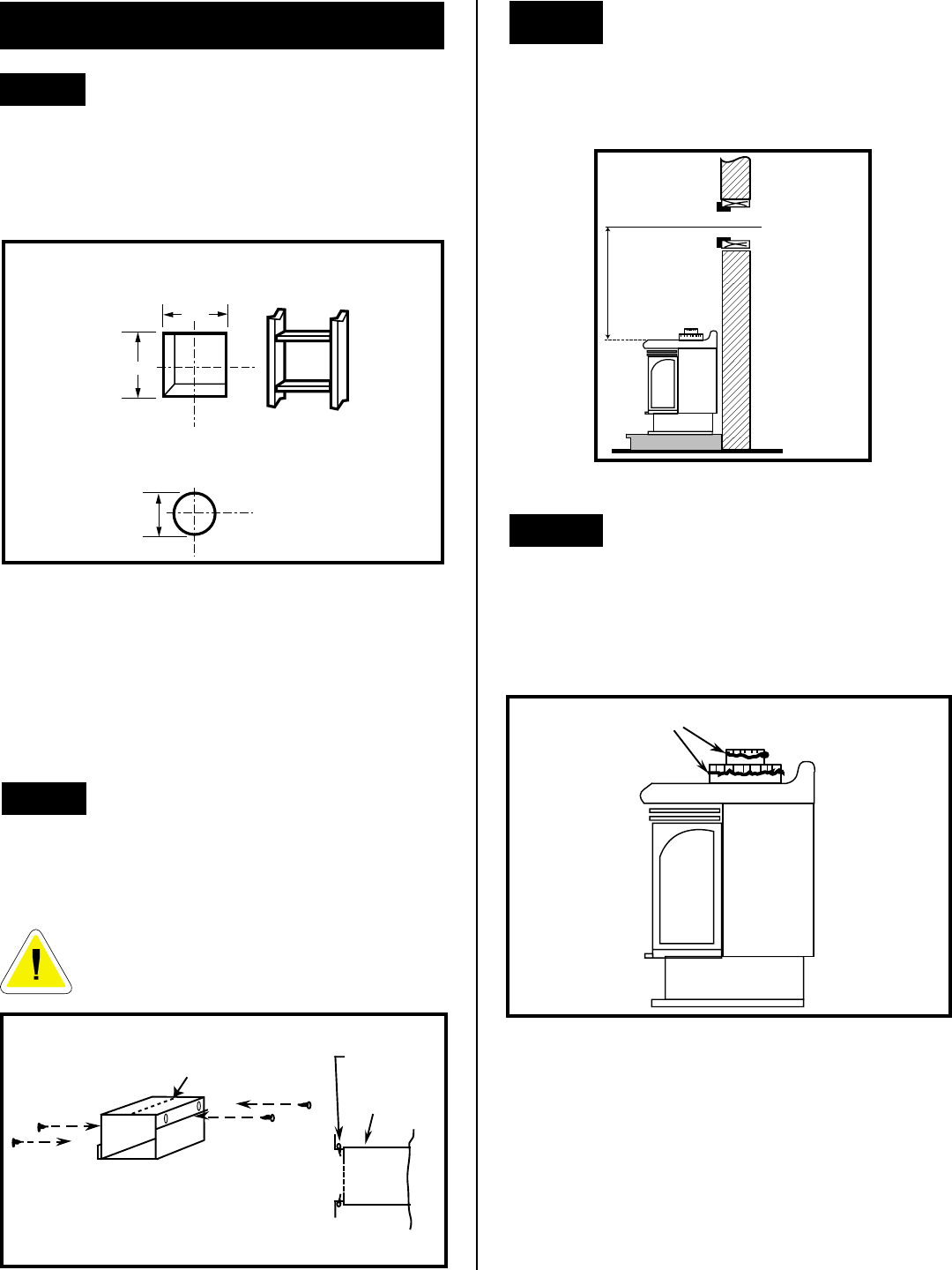
STEP 3
Place fireplace into position. (Fig. 17). Measure the vertical
length (X) required from the base of the flue collars to the
centre of the wall opening.
Fig. 17
X
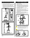
STEP 4
Apply a bead of silicone to the inner and outer flue collars
of the fireplace (Fig. 18) and using appropriate length of
pipe section(s) attach to fireplace with three (3) screws.
Follow with the installation of the inner and outer elbow,
again secure joints as described on page 9.
Fig. 18
BEAD OF SEALANT