


14
CR Series Woodburning Fireplaces
20001316
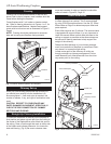
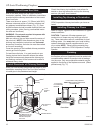
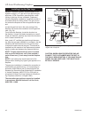
Finish Wall
Finish the wall with material of your choice. Do not
install a combustible mantel shelf less than 12”
(305mm) from the top of the fireplace opening. Do
not install a mantel face plate less than 6” (159mm)
from top of fireplace opening. (Fig. 18)
If a combus-
tible material is used below a flat mantel shelf, consult
your local building codes for minimum clearance from
top of fireplace opening to bottom of mantel shelf.
When finishing the fireplace, a combustible facing ma
-
terial (i.e. drywall or wood paneling) may be installed
at the fireplace surround top as shown in Figure 20.
This material may rest on the ledge brackets (brackets
on the front and side edges of the fireplace), but must
NOT be notched to fit around them. (Fig. 20)
All joints (top, bottom and sides), where the wall or
decorative facing material meets the fireplace sur
-
round must be completely sealed with a noncombus-
tible material. (Fig. 17, 18, 20)
Only noncombustible material may be applied as fac-
ing to the black fireplace surround.
When finishing the fireplace, never obstruct or
modify the air inlet grille in any manner.
When finishing the fireplace, use the material of
your choice. If you decide to cover the fireplace
surround, noncombustible materials must be
used.
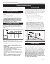
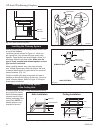
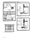
Side Wall Protection
All walls constructed closer than 16” (406mm) from the
fireplace opening must be protected with CFM Corpo-
ration Wall Shield Model SP40 or a built-up wall shield
described in Figure 17.
(ANY PERPENDICULAR SIDE WALL MUST NOT BE
CLOSER THAN 40” (1016mm) TO THE OPEN END
OF AN OPEN END FIREPLACE.)
The built-up wall shield design described in Figure 17
is an alternate method for adding protection to side
walls and can be used in place of the SP40 with the
same wall clearances specified for the SP40.
EXAMPLES OF INSULATION:
1. Manville - CERAFORM 126, K = .27, 1/2” thick
required.
2. CFM Corporation Building Products - EH2416, K =
.458, 1” thick required.
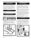
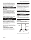
Hearth Installation
A hearth extension is required to protect a combustible
floor in front of the fireplace. Refer to Figure 20 for
minimum dimensions and mounting detail.
NOTE: Hearth Extension must not cover the air
inlet opening of a fireplace.
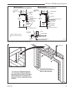
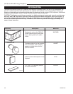
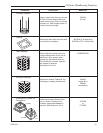
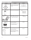
The hearth extension described in Figure 20 must be a
durable non-combustible material with a minimum (to-
tal) Rt value of 1.09; refer to Figure 21 for examples.
The overall height (above a combustible floor), depth
and width must be as indicated, with the extension
centered to the fireplace opening.
The top of the insulation material must be covered with
a noncombustible decorative covering or a piece of
.018” minimum sheet metal, to protect hearth exten-
sion material. (Fig. 23)
Secure the hearth extension to the floor to prevent
shifting, using trim molding or other similar means at
three (3) outer edges. Seal crack between the fire-
place hearth and hearth extension with a noncombus-
tible material. (Figs. 22,23)
WARNING: HEARTH EXTENSION MUST BE
INSTALLED IN ACCORDANCE WITH FIGURES 20
AND 21.
Alternate noncombustible materials may be used pro-
viding the (total) thermal resistance (Rt value) of the
alternate material employed is greater than or equal to
R = 1.09. Thermal resistance (R) or thermal conduc-
tivity (K), may be obtained from manufacturer of the
material. Factors are related by the formula K = 1/R.
T = given thickness
R = thermal resistance for a given thickness (T)
K = thermal conductivity
Noncombustible material with a lower R value may
be used, provided thickness of material is sufficiently
greater to maintain an equivalent (total) thermal resis-
tance (Rt).
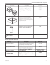
Example of Determining Hearth Extension
Equivalents
To determine the thickness required for any new mate-
rial:
NEW K of new material (per inch) thickness
required = X of listed
thickness K of listed material (per inch) material
Example for Common Brick
T (new) = 5.0/0.458 x .5 in. = 5.46 in. (new required
thickness).