


- 6 -
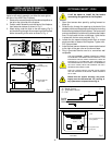
INSTALLATION OF REMOTE
SWITCH FOR RN/RP GAS VALVE
Install on/off switch assembly on either the rear right or
left side of the A232 Gas Fireplace.
1. Remove the screw at the back of the cabinet top either on
the left or the right side of the fireplace.
2. Position switch assembly onto the back of the fireplace,
then fasten two screws as shown in Fig. 5.
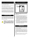
3. Attach wiring under the clips on the rear casing (Fig. 5)
and install wiring through the rear opening of the fireplace
before connecting to the valve as shown in Fig. 4.
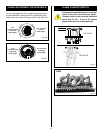
P
I
L
O
T
TPTH
TP
TH
ON/OFF SWITCH OR
MILLIVOLT THERMOSTAT
VALVE
THERMOPILE
Screw
(through existing hole)
Screw
On/off switch
assembly
Clips
Wiring for milli-volt
gas valves
Fig. 5
A
B
C
BLACK
WHITE
GROUND
A = Speed Control
B = Temperature Sensor
C = Fan
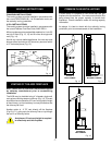
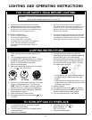
OPTIONAL FAN KIT - FK24
It will be easier to install the fan before
connecting the gas line to the fireplace.
1. Open front access door panel by pulling forward on
brass lip.
2. Guide the fan through the opening at the back of the
pedestal, with the outlet pointed up and the fan mounting
bracket facing the back of the fireplace. The fan mounts
over two studs which hold the fan just below the firebox
floor. Do not install this fan on the base. Hold the fan
in place with the two nuts provided. (Fig. 7)
3. Locate the fan speed control/junction box on screw
studs provided on base of the fireplace. Tighten with
3/8" nuts provided.
4. Install thermal sensor element on screw studs located
to the right of the gas valve on the burner base.
5. Plug in grounded service cord to a convenient wall
receptacle.
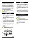
THIS FAN ASSEMBLY COMES COMPLETELY WIRED
TO ELIMINATE THE NEED FOR ELECTRICIANS. THIS
ELECTRICAL DEVICE, WHEN INSTALLED, MUST BE
ELECTRICALLY CONNECTED AND GROUNDED IN
ACCORDANCE WITH LOCAL CODES. IN THE ABSENCE
OF LOCAL CODES, WITH THE CURRENT CSA C22.1
CANADIAN ELECTRICAL CODE.
FOR U.S.A. INSTALLATION: FOLLOW LOCAL CODES
AND THE NATIONAL ELECTRICAL CODE ANSI/NFPA
NO.70-1984.
Fig. 6
Fig. 7
Should this fan require servicing, the power
supply must be disconnected. For rewiring of
any replacement components see Fig. 6.
TOP VIEW
Valve
Fan speed control/
Junction box
Thermal sensor
location
Fan is installed at the back
of the pedestal
Stud
PILOT
ADJ
TH
TP
TP
TH
Fig. 4