


11
UVS27 Vent-Free Gas Heater
20007068
2. Hold the burner at the right hand side and lift to clear
the right burner leg. Then pull to the right to clear the
injectors on the left hand side.
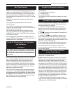
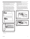
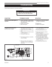
3. Turn burner upside down and remove air shutter.
Turn air shutter upside down and replace on burner.
(Fig. 13)
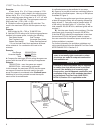
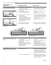
4. Replace burner. Slide the burner in at an angle
with left side lower than the right side. Slide the left
side onto the injectors, making sure the burner leg
remains at a 90° angle to the base. (Fig. 14) Lower
the right hand side down in to place. Make sure
the burner is as far left as possible and the injector
shoulders are inside the burner.
ST667
RNVOD
air shutter
converting
from NG to Lp
6/4/01 djt
Air Shutter as Shipped from Factory
Bottom of Burner Pan
ST667
Fig. 13 Remove air shutter, turn upside down and replace.
Air Shutter Turned Upside Down
ST353a
injector orifice
replace
3/21/00 djt
90°
Left Burner Leg
Injector Orifices
ST353a
Fig. 14 Be sure injector orifices remain at 90° to the base.
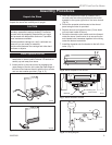
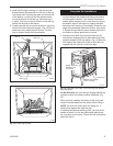
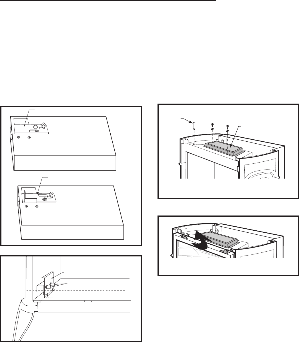
6. Slide the catalyst through the grille opening. Set
catalyst on top of firebox. Secure with two (2) screws
and washers. (Fig. 15)
7. Shoulder bolts provided in catalyst kit must be in
-
stalled on top of firebox. Use nut to secure in place.
(Fig. 15)
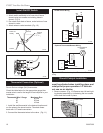
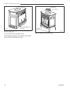
8. Install glass frame assembly by resting the bottom
edge of the frame on support brackets below the
front opening of the firebox. Rotate the top edge of
the assembly toward the firebox, and center it. Fas-
ten by “rotating” the cams over the top left and right
edges of the frame. (Fig. 16)
5. Replace rear, left and right log bracket assembly and
replace logs.
ST709
UVS pin
top install
1/29/02 djt
Shoulder
Bolts
ST709
Fig. 15 Install shoulder bolts and set catalytic combustor in
place.
Catalytic Combustor
NOTE: Shown with top
removed for clarification.
ST711
Fig. 16 Rotate cams into place to hold glass frame assembly
in place.
NOTE: Shown with top
removed for clarification.
ST709
UVS pin
top install
1/29/02 djt