


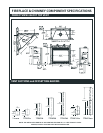

33-1/2"
29-5/8"
(753mm)
2 x 4's
2 x 4
Header
2 x 4
2 x 4
14-1/2"
(368mm)
33-1/2"
MINIMUM FRAMING DIMENSIONS
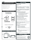
FLUE SYSTEM
7” Coaxial Direct Vent S
y
ste
m
SPECIFICATIONS:
• 7” O.D.
• 4” I.D.
MINIMUM CLEARANCE TO COMBUSTIBLE MATERIAL
a) Vertical Side Wall Applications 1” to All Sides
b) Vertical thru the Roof Applications 1” to All Sides
MINIMUM COMBUSTIBLE WALL/FLOOR OPENINGS
M
AXIMUM INSTALLATION LENGTHS
a) Vertical Side Wall Applications
36” (914 mm) Horizontal Vent Length with 90°
elbow installed directly on top of the unit
20ʼ (6 m) Horizontal Vent Length with
7.5ʼ (2.29 m) vertical rise
*Refer to manual for alternative venting distance
*Maximum angular variation for Vertical Sidewall/Vertical
Application in system is total of 270°
*Refer to installation manual for all venting restrictions
with elbow use
TERMINATION CLEARANCES MINIMUM
a) Horizontal
12” (305 mm) above Grade Level
18” (458 mm) to Ventilated Soffi t
12” (305 mm) to Unventilated Soffi t
12” (305 mm) under veranda, porch,
deck or balcony
b) Vertical
24” (610 mm) Above a Roof Surface and any other
obstruction within a horizontal distance
of 18” (458 mm)
33LDVT ANSI Z21.88 - 2005/CSA 2.33 2005
Vented Gas Fireplace Heaters
This gas appliance should be installed by qualifi ed installers
in accordance with local building codes and the current
National Fuel Gas code ANSI Z223.1 or CSA B 149.1
Installation code for Gas Burning Appliance and Equipment.
PRODUCT LISTING
OPTIONAL ACCESSORIES (Continued):
(Trim Kits continued from second page)
WALL FRAMING DIMENSIONS
Vent Opening for
Combustible Wall
• Louver Kits - Additional Louver Kits ( To replace all louvers in
desired color, 4 sets are required ) See Price List
• Filligree Louver Kits - See Price List
• Perimeter Trim Kits - See Price List
• Face Trim Kits - See Price List
Framing Detail
9³⁄₈"
(240 mm)
9³⁄₈"
(240 mm)
VO584-100
Fireplace Hearth
Rnd.
7¹⁄₂" Dia.
(190 mm)
Opening for Non-combustible Wall
a) 9 3/8” W x 9 3/8” H for Vertical Side Wall/Vertical
Applications
VERTICAL THRU THE ROOF APPLICATIONS
• 8ʼ (2.4 m) Minimum Vertical Rise
• 40ʼ (12 m) Maximum Vertical Rise
• 2 sets of 45° Elbows can be used in Vertical
rise with 8ʼ maximum distance between elbows
• Two 90° elbows maximum for 10ʼ (3 m)
Horizontal can be installed in Vertical Applications
*Refer to installation manual for more termination
restrictions
(851mm) (851mm)