


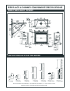

FIREPLACE & CHIMNEY COMPONENT SPECIFICATIONS
PERFECTVIEW 33LDVT TOP VENT
VENT SECTIONS and OFFSETTING ELBOWS
NOTE: THE INSTALLED LENGTH OF ANY VENTING SECTION IS 1
1/2
” LESS THAN ITS TOTAL
LENGTH, EXCEPT FOR THE LAST SECTION INSTALLED.
12"
305mm
24"
610mm
36"
914mm
48"
1219mm
7TDVP8
7TDVP12
7TDVP24
7TDVP36
7TDVP48
7TDVP1218
7TDVP3564
8"
203mm
7"
178mm
35"
889mm
64"
1626mm
12"
305mm
18"
457mm
9
1/4
"
7
1/4
"
9
1/4
"
90°
7
"
13"
9
1/4
"
90
°
13"
7
1/4
"
13"
17
"
OFFSET
235mm
235mm
178mm
184mm
330mm
330mm
335mm
330mm
184mm
OFFSET w/2-90°
Back to Back
FIREPLACE FACTS
PerfectView 33LDVT
CONTEMPORARY TERMINATIONS
7TDV45
7TDVRT90
11"
7
3/8
"
45°
45°
7
3/8
"
OFFSET w/2-45°
Back to Back
45°
7
3/8
"
188mm
188mm
188mm
FP890
FP889
ELBOWS
7TDVRVT
7TRVT
9³⁄₄"
12¹³⁄₁₆"
7"
7TDVSKV
9¹⁄₂"
7"
13³⁄₁₆"
7TDVSKS
32"
6
1/2
"
813mm
127mm
19"
16"
482mm
406mm
165
mm
5
"
33” PerfectView Direct Vent Gas Appliance
FEATURES:
• 33
”
PerfectView Direct Vent Gas Appliance
• 11,200 to 16,000 BTU/hr. input
• Patented Insta-Flame TM Ceramic Burner System with 4-piece
Split Oak Ceramic Fiber Log Set
• Tempered Glass Panel Assembly
• Adjustable Flame and Heat Output
• Wall Switch
• 18
”
Flex Connector with Shutoff and EB1 electrical box installed
• Wall Firestop, Zero Clearance Sleeve (Rear vent models only)
• Rated as Fireplace Heater (AFUE)
• Uses 4
”
/7
”
Majestic (Direct Vent) Venting Components.
BURNER SYSTEM:
• Capacity – Natural: 16,000 BTU/HR Max.
11,200 BTU/HR Min.
– Propane: 16,000 BTU/HR Max.
12,000 BTU/HR Min.
• Fuel - Natural or Propane Gas
• Ignition System - Standing Pilot With Piezo Ignitor, A Low Voltage,
Self-Generating Power Pile System (mV)
– No Outside Electrical Power Needed OR
– Electronic ignition that requires 120 VAC Electrical hook up
• Gas Supply Line -
Consult Gas Code Book for Correct Sizing
• Gas Inlet and Manifold Pressures
Natural Propane
Minimum Inlet Pressure 5.5” w.c. 11.0” w.c.
Maximum Inlet Pressure 14” w.c. 14.0” w.c.
Manifold Pressure 3.5” w.c. 10.0” w.c.
MINIMUM FLOOR AREA:
• 33” W X 14” D
HEARTH EXTENSION:
A Hearth Extension Is Recommended But Not Required
ACCESSORIES:
33LDVTCR - 33” LDV Ceramic Refractory - Top
FK12 - Fan and Cord (160cfm) (for RN/RP only)
FK24 - Variable Speed Heat-Activated Fan Kit
IMTFK - IMT Thermostat w/ Face Kit
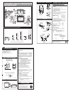
33-1/2"
29-5/8"
(753mm)
2 x 4's
2 x 4
Header
2 x 4
2 x 4
14-1/2"
(368mm)
33-1/2"
MINIMUM FRAMING DIMENSIONS
FLUE SYSTEM
7” Coaxial Direct Vent System
SPECIFICATIONS:
• 7” O.D.
• 4” I.D.
MINIMUM CLEARANCE TO COMBUSTIBLE MATERIAL
a) Vertical Side Wall Applications 1” to All Sides
b) Vertical thru the Roof Applications 1” to All Sides
MINIMUM COMBUSTIBLE WALL/FLOOR OPENINGS
MAXIMUM INSTALLATION LENGTHS
a) Vertical Side Wall Applications
36” (914 mm) Horizontal Vent Length with 90°
elbow installed directly on top of the unit
20? (6 m) Horizontal Vent Length with
7.5? (2.29 m) vertical rise
*Refer to manual for alternative venting distance
*Maximum angular variation for Vertical Sidewall/Vertical
Application in system is total of 270°
*Refer to installation manual for all venting restrictions
with elbow use
TERMINATION CLEARANCES MINIMUM
a) Horizontal
12” (305 mm) above Grade Level
18” (458 mm) to Ventilated Soffi t
12” (305 mm) to Unventilated Soffi t
12” (305 mm) under veranda, porch,
deck or balcony
b) Vertical
24” (610 mm) Above a Roof Surface and any other
obstruction within a horizontal distance
of 18” (458 mm)
33LDVT ANSI Z21.88 - 2005/CSA 2.33 2005
Vented Gas Fireplace Heaters
This gas appliance should be installed by qualifi ed installers
in accordance with local building codes and the current
National Fuel Gas code ANSI Z223.1 or CSA B 149.1
Installation code for Gas Burning Appliance and Equipment.
PRODUCT LISTING
908mm
578mm
851mm
1283mm
641mm
368mm
356mm
152mm
753mm
118mm
162mm
838mm
466mm
794mm
806mm
733mm
118mm
162mm
225mm
ACCESSORIES (Continued):
(continued from second page)
WALL FRAMING DIMENSIONS
Vent Opening for
Combustible Wall
• Louver Kits - Additional Louver Kits ( To replace all louvers in
desired color, 4 sets are required ) See Price List
• Filligree Louver Kits - See Price List
• Perimeter Trim Kits - See Price List
• Face Trim Kits - See Price List
• NEW - Bulk Flex Vent Kits - See Price List
Framing Detail
9³⁄₈"
(240 mm)
9³⁄₈"
(240 mm)
VO584-100
Fireplace Hearth
Rnd.
7¹⁄₂" Dia.
(190 mm)
Opening for Non-combustible Wall
a) 9 3/8” W x 9 3/8” H for Vertical Side Wall/Vertical
Applications
VERTICAL THRU THE ROOF APPLICATIONS
• 8? (2.4 m) Minimum Vertical Rise
• 40? (12 m) Maximum Vertical Rise
• 2 sets of 45° Elbows can be used in Vertical
rise with 8? maximum distance between elbows
• Two 90° elbows maximum for 10? (3 m)
Horizontal can be installed in Vertical Applications
*Refer to installation manual for more termination
restrictions
51mm
86mm
908mm
(851mm) (851mm)
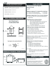
Minimum Mantel Clearances
Mantel Depth
2”
4”
6”
8”
10”
Clearance From Top
of Combustion Chamber Opening
To Bottom of Mantel
8
1/2
”
10
1/2
”
12
1/2
”
14
1/2
”
16
1/2
”
REV. 10/07
The Fireplace Facts Information Sheets are for
quick reference only and are subject to change with-
out notice. Actual fi replace instructions must abide
by specifi cations provided with each product.