


8
Vermont Castings Pinnacle & Stardance Direct Vent - Rear Vent Gas Heaters
20003457
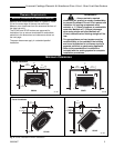
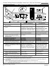
Vent Termination Clearances
When planning the installation, consider the location of
the vent terminal and clearances. Some of the most
common clearances to keep in mind are shown in
Figure 9.
Important: All vent clearances must be maintained.
Check your vent termination clearances against
Figures 9 and 10 .
The vent should be placed so that people cannot be
burned by accidentally touching the vent surfaces
when the stove is operating.
The vent termination should be located where it cannot
be damaged by such things as automobile doors, lawn
mowers or snowblowers and it should be located away
from areas where it could become blocked by snow,
etc.
Some considerations are:
• Obstructions or impediments to venting.
• Nearby combustible materials that could come into
contact with combustion exhaust gases.
• Other nearby openings {within 9" (230mm)} through
which exhaust gas could reenter the building.
• All vegetation within 3' (.9m) that may interfere with
the draft.
Other factors that influence where the installation will
be sited include the location of outside walls, where
additional heat may be desired in the home, where the
family members gather most regularly, and perhaps
most importantly, the distance limitations of the venting
system.
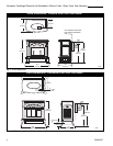
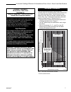
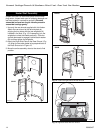
Vertical Termination
A vertical vent system must terminate no less than 8'
(2.44m) and no more than 40’ (12m) above the appli-
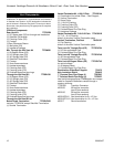
ance flue collar. A 2¹⁄₄" restrictor plate (supplied) must
be used (where specified) in all vertically terminated
vent systems. NOTE: The restrictor plate supplied
with the vertical termination should be discarded.
Install restrictor plate supplied with stove directly
at stove outlet. A vertically terminated vent system
must also conform to the following criteria:
• No more than three 90° elbows may be used.
90° elbow off back must be transition elbow.
•Two 45° elbows may be substituted for one 90°
elbow. No more than six elbows may be used.
•Vent must rise a minimum of 2 feet before offset is
used.
•Termination height must conform to roof clearance as
specified in Figure 9.
20
19
18
16
15
14
13
12
11
10
9
8
7
6
5
4
3
2
1
0
20
1 2345678910111213141516171819
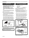
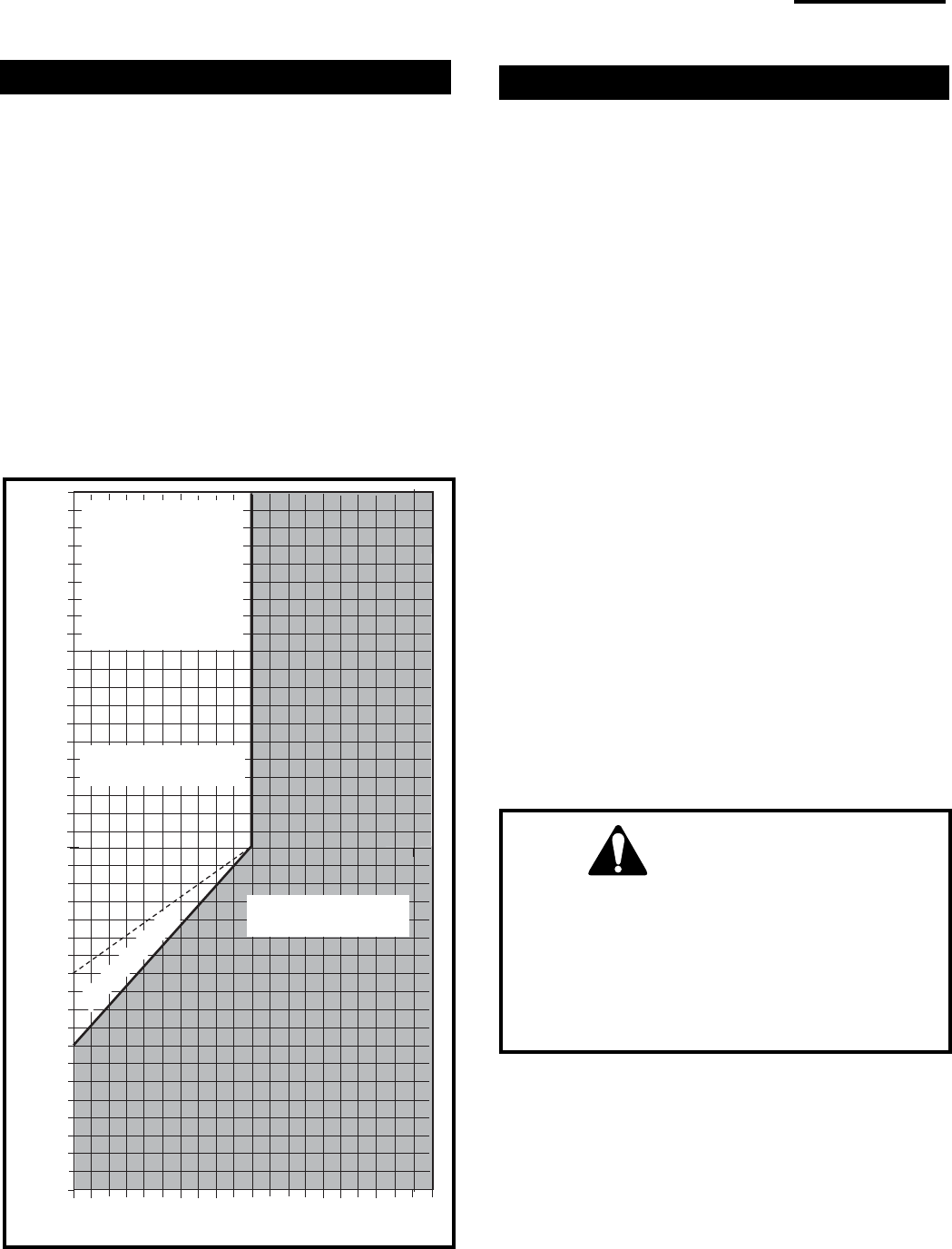
Vertical Run (in feet)
(Measured after the first elbow. (Transition elbow)
Horizontal Run (in feet)
21
22
23
24
25
26
27
28
29
30
31
32
33
34
35
36
37
38
39
40
ST132f
Fig. 8 Vertical vent termination window.
All Vertical
Terminations in
this area Re-
quire use of the
2¹⁄₄” Restrictor
Plate*
Vertical terminations
must be within this area
Unacceptable
Venting Configuration
No Restrictor Plate
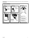
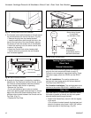
IMPORTANT
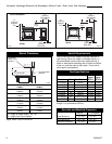
• The horizontal termination must not be recessed
into the exterior wall or siding.
• Horizontal vent runs must be level toward the
vent termination.
• Clearances around the vent termination must be
maintained.