


15
Vermont Castings Pinnacle & Stardance Direct Vent - Rear Vent Gas Heaters
20003457
Install the Firebox
NOTE:
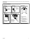
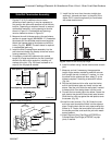
Dry fit the Starter Pipe and first vent pipe
sections to the flue collar to align and drill pilot
holes as necessary, while the firebox is on the
shipping pallet. You will not be able to drill holes
after the firebox is installed.
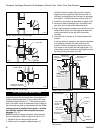
Also, you will find it easiest to connect the
flexible or hard gas supply pipe to the burner
control valve before installing the firebox into the
shell.
1.
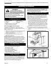
Remove any cardboard packing material from the
top of the firebox.
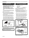
Double-check to be sure the sides
align at 90
°
to the rear shroud.
NOTE: The firebox is shipped with three bolts and
spacers on the bottom to prevent the assembly on
the bottom of the firebox from being damaged. The
two front bolts should be removed after installation
using a 7/16” wrench.
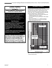
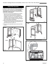
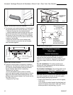
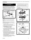
2. Lift the firebox assembly and slide it back into
position in the shell. The base of the firebox should
rest on the side support shelves as in Figure 16.
A pair of steel tabs will engage a mating rib on the
top side of the outer edges of the firebox base as
shown in Figure 16. Properly positioned, the firebox
will be level and locked in place. If not, adjust the
levelling screw in the foot of each leg as needed.
ST125
Firebox washer align
10/15/99 djt
ST125
Steel Tab
Side Plate
Support Shelf
Base
Fig. 16 Install firebox assembly.
If you are not installing a fan, proceed to the
appropriate vent assembly section.
Install Optional Fan Kit #2960/FK28
Fan Kit Contents:
• #10 x 1/2" phillips screws, 6
• Control Knob
• Retainer Collar
• Snapstat • Snapstat Bracket
• Blower Assembly w/ Rheostat Control
NOTE: The Rheostat Assembly and the Snapstat
Assembly are not used on RF Models.
For RF Models only: Follow Step 3, then run the
spliced female leads to the front of the stove and attach
to PC board of RF valve. Then follow Step 5.
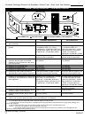
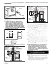
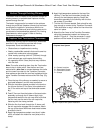
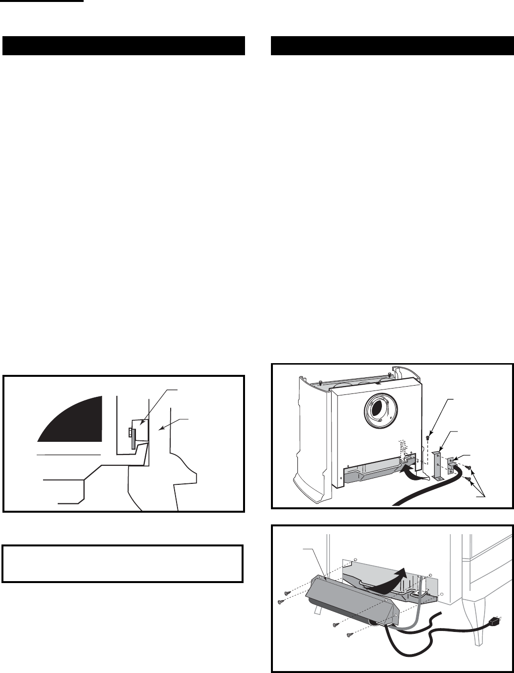
1. Attach the Snapstat to the Bracket using two #10 x
1/2" phillips sheet metal screws as shown in Figure
18.
2. Locate and remove the 1/4-20 x 3/8" hex head bolt
installed in the hole in the right rear ledge of the
firebox. (Fig. 17) Use that bolt to secure the Snapstat
Bracket to the firebox. The mounting hole is slotted
to allow you to adjust the bracket so that its head
makes contact with the firebox surface. (Fig. 17)
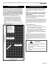
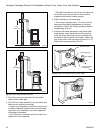
3. Attach the Fan to the firebox by engaging the upper
flange of the fan skirt under the lower edge of the
Shroud and secure the skirt with the four screws
provided with the kit. (Figs. 18, 19)
Upper
Flange
ST240
Fig. 18 The upper flange of the fan skirt should be located
behind the lower edge of the shroud.
1/4-20 x 3/8”
Hex Head Bolt
Bracket
Snapstat
1/2” Sheet
Metal Screws
FK101
Fig. 17 Snapstat assembly and installation.