


40
Vermont Castings Pinnacle & Stardance Direct Vent - Rear Vent Gas Heaters
20003457
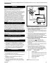
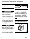
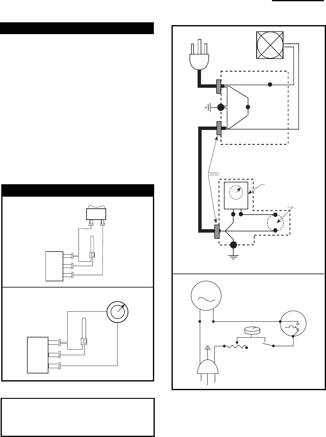
FAN JUNCTION BOX
FAN
Strain Relief
Chassis Ground
BLK
GRN
GRN
WHT
ON / OFF
Rheostat
Chassis
Ground
Snapstat
BLK
BLK
BLK
BLK
BLK
WHT
RHEOSTAT / SNAPSTAT
BOX
POWER
CORD
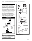
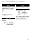
Fig. 83 PDV20/SDVR fan circuit.
MOTOR
SNAPSTAT
ON/OFF
RHEOSTAT
WHT
WHT
BLK
BLK
BLK
GRN
BLK
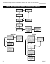
Schematic Diagram
ST234
ST153
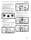
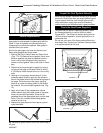
Stove Disassembly
If there is ever a need to remove the firebox assembly
from the stove shell, support the firebox with solid
stands about 6” (150mm) tall under the left and right
outer edges of the firebox base. Do not set the firebox
assembly directly on the floor; this can damage the
control valve and/or the gas lines from the valve to the
firebox.
Before removing the firebox from the shell, disconnect
the on/off switch wires from the valve. If the assembly
includes the optional fan, disconnect the fan rheostat. If
the installation includes a wall thermostat, disconnect
the thermostat leads from valve.
Disconnection and reconnection to the gas line should
only be done by a qualified gas service technician.
Upon reinstallation, the vent system must be sealed to
the firebox as shown in the installation section, page
18. Also be sure the logs are placed in the firebox
correctly, as shown in Figures 51-54, page 27.
NOTE: IF ANY OF THE ORIGINAL WIRE, AS SUP-
PLIED WITH THE APPLIANCE, MUST BE RE-
PLACED, IT MUST BE REPLACED WITH TYPE SF-
2, 200°C WIRE OR ITS EQUIVALENT.
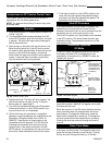
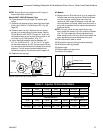
Wiring Diagrams
ST124c
Fig. 82 PDV20/SDVR on/off switch and optional thermostat
circuit.
Optional Thermostat
Wiring
On/Off Switch
Wiring
ST124b
OFF
ON
Thermopile
Black
Black
TP/TH
TP
TH
Thermostat
(Optional)
Therm
opile
Black
Black
TP/TH
TP
TH