


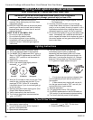
2222
Vermont Castings Jefferson Direct Vent/Natural Vent Gas Heater
20002191
ST229a
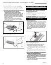
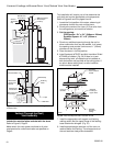
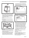
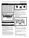
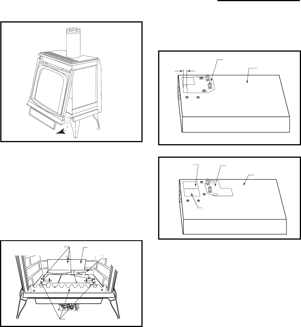
Fig. 37 Remove stove front.
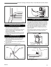
3. Pull the top edge of the glass and frame assembly
away from the firebox, and lift it off its supports on
the bottom of the firebox face. Place the assembly
out of the way on a flat, padded surface such as a
counter protected by a towel.
4. Take the logset out of the firebox if previously in-
stalled.
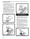
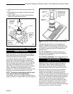
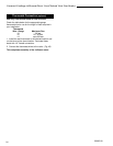
5. Remove the rear log bracket by unfastening the
screw. (Fig. 38)
6. Remove the right and left log bracket assembly by
unfastening the two screws which hold the burner in
place. (Fig. 38)
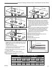
Remove Screws
Rear Log Bracket
Pilot
Left & Right Log
Bracket Assembly
ST350
Fig. 38 Remove rear log bracket and left and right log
bracket assembly.
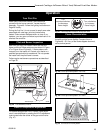
7. Hold the burner at the right hand side and lift to clear
the right burner leg. Then pull to the right to clear the
injectors on the left hand side.
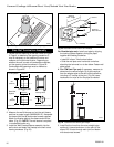
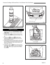
8. The air shutter is located on the bottom of the burner
to the left. (Fig. 39) Unfasten the two nuts holding
the shutter in place. The shutter may be adjusted
between the factory adjusted 1/2” to fully open.
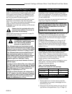
Reassemble the shutter to allow the rear injector air
inlet to close from a minimum 1/2” opening to fully
open. (Fig. 40) You may have to try more than once
to find the correct air shutter opening for best results
depending on your altitude.
9. Refasten the two nuts and assemble the burner into
the unit by sliding the burner in at an angle with the
left side lower than the right side. Slide the left side
onto the injectors. Lower the right hand side down
into place. Make sure the burner is as far left as
possible and the injector shoulders are inside the
burner. NOTE: It is very critical to keep the left
burner leg, which holds the injectors, at a 90° angle
to the base. (Fig. 41) This keeps the orifices aligned
with tubes on the inside of the burner. Failure to do
so could affect the flame appearance and perfor-
mance of the unit.
10.Refasten the right and left log bracket assembly.
11.Refasten the rear log bracket.
12.Replace logs.
13.Replace glass and stove front.
Follow lighting instructions on page 26. Check flame
color appearance. NOTE: Allow stove to burn for at
least 1/2 hour to establish full flame color.
Should color need further adjustment, repeat steps 1 -
12 for air shutter adjustment.
Air Shutter
(Original Position)
Burner
ST352
Fig. 39 Air shutter in original from-the-factory position.
See Table 1
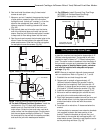
Front Injector
Air Inlet
Air Shutter
(May be adjusted up to fully open)
Burner
Rear Injector Air Inlet
ST351
Fig. 40 Air shutter adjusted.