


17
Vermont Castings Jefferson Direct Vent/Natural Vent Gas Heater
20002191
6. Seal and install the elbow using 3 sheet metal
screws at each joint.
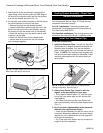
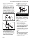
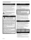
7. Measure, and cut if needed, the appropriate length
of pipe section needed to make the connection
through the wall. Include a 2” overlap; i.e. from the
elbow to the outside wall face, about 2” or the
distance required if installing a second 90° elbow.
(Fig. 25)
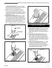
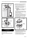
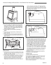
8. Slip the wall plate and trim collar over the interior
end of the horizontal pipe and install into the wall
sleeve. Seal the joint inside the wall plate if needed
to keep cold air from being drawn into the home.
9. Seal the ends and connect the horizontal pipe to the
elbow. Fasten the wall plate to the pipe with three
sheet metal screws. Slide the trim collar up against
the wall plate to cover the screws. (Fig. 26)
X
ST215
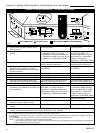
Fig. 25 Measure the horizontal length.
Trim Collar
Wall
Sleeve
Wall Plate
ST216
Fig. 26 Install the horizontal pipe and wall plate parts.
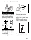
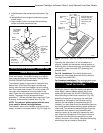
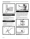
10. For both CFM and DuraVent Systems:
Install the
vent terminal. (Fig. 27) Apply high temperature
sealant one inch from the ends of the inner and
outer collars. Guide the inner and outer vent termi-
nation collars into the adjacent pipes. Double check
that the vent pipes overlap the collars by 2”. Fasten
the termination to the wall with the screws provided,
and caulk the joint with weatherproof sealant.
11. For CFM only:
Install Charcoal Gray Pipe Rings
(#7FSDRG) or Polished Brass Pipe Rings
(#7FSDRP) at pipe joints, if desired.
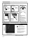
Seal Both
Terminal Ends
Caulk Plate Joint with
Weatherproof Sealant
ST217
Fig. 27 Install the vent terminal.
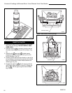
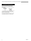
Vent Termination Below Grade
Install Snorkel Kit #7FSDVSKS when it is not possible
to meet the required vent termination clearances of 12”
(305mm) above grade level. The snorkel kit will allow
installation depth of down to 7” (178mm) below grade
level. The seven inches is measured from the center of
the horizontal vent pipe as it penetrates the wall. If the
venting system is installed below grade, a window
well must be installed with adequate and proper
drainage. (Fig. 28)
NOTE: Be sure to maintain side wall clearances and
vent run restrictions. Refer to Figures 3, 4, 7, and 8.
1. Establish the vent hole through the wall.
2. Remove soil to a depth of approximately 16”
(400mm) below the base of the snorkel. Install a
window well (not supplied). Refill the hole with 12”
(305mm) of coarse gravel and maintain a clearance
of at least 4” (100mm) below the snorkel. (Fig. 28)
3. Install the vent system as described on pages 15-18.
4. Be sure to make a watertight joint around the vent
pipe joint at the inside and outside wall joints.
5. Apply high temperature sealant around the inner and
outer snorkel collars. Join the pipes and fasten the
snorkel termination to the wall with the screws
provided.
6. Level the soil to maintain a 4” clearance below the
snorkel.
If the foundation is recessed, use extension brackets
(not supplied) to fasten the lower portion of the
snorkel. Fasten the brackets to the wall first, and
then fasten to the snorkel with self-tapping #8 x 1/2”
sheet metal screws. Extend the vent pipes out as far
as the protruding wall face. (Fig. 29)