


13
Vermont Castings Jefferson Direct Vent/Natural Vent Gas Heater
20002191
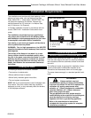
Assembly Procedures
Failure to position the parts in
accordance with these diagrams or
failure to use only parts specifically
approved for use with this heater may result in
property damage or personal injury.
This heater and components are heavy. Have
help available for assembly.
WARNING
Tools Required
• Phillips screwdriver (stub) • power drill
• utility knife • reciprocating saw
• metal drill bit: size 28 (.140”/3.5mm)
Unpack the Stove
The parts bag containing this manual also includes the
following parts:
• Remote Switch • Switch Bracket
• Switch Wire • Three 1/4-20 x 3/8” screws
• Cement • Restrictor Plate
• (2) #10 sheet metal screws
The Logset and 4” Inner Vent Starter Pipe are packed
inside the firebox. Use the following procedure to
unpack these parts.
1. Lift the Stove Front up and then swing the bottom
out and away to disengage it from the stove body.
Refer to Figure 37, Page 22.
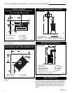
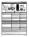
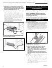
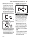
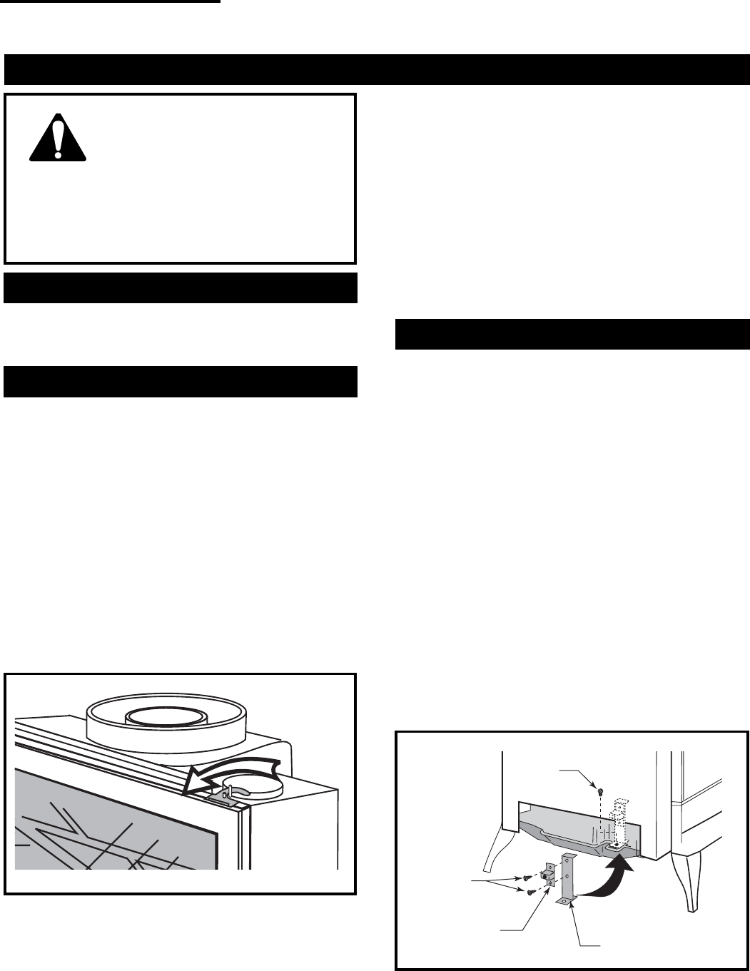
2. Swing open the swiveling latches at the top left and
right corners of the glass frame. (Fig. 12)
ST208
Fig. 12 Swivel the latches to release the glass frame from
the firebox.
3. Pull the top edge of the glass and frame assembly
away from the firebox, and lift it off its supports on
the bottom of the firebox face. Place the assembly
out of the way on a flat, padded surface such as a
counter protected by a towel.
4. Take the logset and all other loose parts out of the
firebox, and set them aside in a protected area for
installation after the venting is complete.
NOTE: Verify the two relief doors (located on top of
the firebox) are properly seated on the gasket. The
doors should sit flush on the gasket, and should lift
easily from the seal around the opening.
Install the Optional Fan
If you are installing the optional convection Fan Kit
#2960 (FK28), continue here. If you will not install a
Fan Kit, go to page 14, Venting System Assembly.
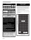
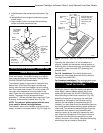
1. The fan kit includes a Blower Assembly and a
Rheostat Assembly, connected by a cable. (Fig. 14)
The Blower Assembly and the Rheostat mount to the
rear shroud of the stove. The assembly includes a
‘snapstat’ which automatically turns the fan ON (or
OFF) above (or below) approximately 109°F (43°C).
The Rheostat also provides a range of fan speed
settings from Off (which overrides the snapstat
function ) to HIGH. Unpack and inspect the Blower
assembly. Confirm that the fan spins freely.
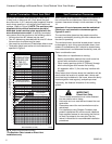
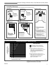
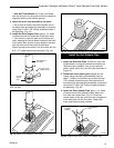
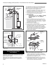
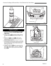
2. Attach the snapstat assembly to the snapstat bracket
with two sheet metal screws. (Fig. 18) Remove the
1/4-20 x 3/8” hex head bolt installed in the hole in the
right rear ledge of the firebox. Use that bolt to secure
the snapstat bracket to the firebox. The mounting hole
is slotted to let you adjust the bracket so that the
snapstat bracket head makes contact with the firebox.
(Fig. 13)
1/4-20 x 3/8”
Phillips
Screw
1/2” Sheet
Metal Screw
Snapstat
Snapstat Bracket
ST239
Fig. 13 Snapstat assembly and installation.