


11
Vermont Castings Jefferson Direct Vent/Natural Vent Gas Heater
20002191
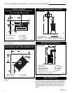
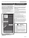
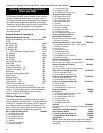
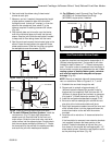
Venting Requirements - Natural Vent Only
Venting Runs
Horizontal Run (in feet)
Vertical Run (in feet)
(Measured from floor of unit to
top of vent cap.)
A: Vertical installations up to 36 feet (12m) in
height. Up to an 18 ft. horizontal vent run can be
installed within the vent system using a
maximum of two 90-degree elbows or four
45-degree elbows.
B: Vertical installations up to 36 feet (12m) in
height. Up to a 24 ft. horizontal vent run can be
installed within the vent system using a
maximum of two 45-degree elbows.
(Ratio = 2/3, Hor./Vert.)
= Acceptable venting configuration
= Unacceptable venting configuration
36
34
32
30
28
26
24
22
20
18
16
14
12
10
8
16 18 20 22 24 26 28 30 32 34 36 4 6 8 10 12 14
A
B
Fig. 11 Vent termination window - Natural Vent ONLY.
FP567b
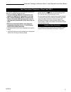
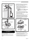
NOTE: When using the FSDHAG, the restrictor plate
supplied with the stove is not used.
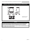
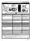
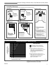
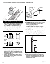
Outside Corner
Inside Corner
Termination Clearances
Termination clearances for buildings with combustible and noncombustible exteriors.
A =
Combustible
6"(152mm)
Noncombustible
2"(50mm)
B =
Combustible
6"(152mm)
Noncombustible
2"(50mm)
A
Balcony -
with no side wall
G =
Combustible&
Noncombustible
12"(305mm)
G
Balcony -
with perpendicular side wall
H = 24"(610mm)
J = 20"(508mm)
H
J
B
Recessed Location
C = Maximum depth of 48"
(1219mm) for recessed
location.
D = Minimum width for back wall
of a recessed location.
Combustible 38"(965mm)
Noncombustible 24"(610mm)
E = Clearance from corner in
recessed location.
Combustible 6"(152mm)
Noncombustible 2"(50mm)
C
D
C
E
V
V
Combustible &
Noncombustible
V
V
V
584-14
Fig. 10 Termination clearances.