


8
Encore Multi-Fuel Heater
2000971
• The fireplace damper must be sealed to prevent
room air from escaping up the flue. However, it must
be possible to reopen the damper to inspect or clean
the chimney.
Through the Fireplace
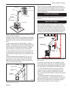
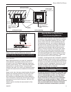
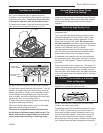
If your fireplace opening height is at least 26¹⁄₂"
(675mm), you may install an Encore Multi-Fuel through
the opening using a “positive connection” kit, available
from your local dealer. These positive connection kits
ensure a tight fit between the stove flue collar and the
chimney flue. (Fig. 8)
Fireplace installations, whether connected to the flue
above or through the fireplace opening, have special
clearance requirements to adjacent trim and the mantel.
Floor protection requirements also apply to fireplace
installations. Refer to “Floor Protection” section.
ST245
fireplace
flex connector
12/99
Flexible Connector
Mantel Shield
Fireplace Adapter
Kit “Positive Con-
nection”
ST245
Fig. 8 In this installation, the chimney connector enters the
firepalce opening and then connects to the chimney.
T
ST494
steel
wall pass thru
11/00
ST494
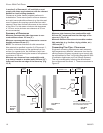
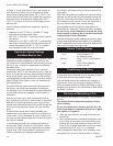
Fig. 9 A hollow wall pass-through method.
Wall Pass-Throughs
Whenever possible, design your installation so the con-
nector does not pass through a combustible wall. If you
are considering a wall pass-through in your installation,
check with your building inspector before you begin.
Also, check with the chimney connector manufacturer
for any specific requirements. Some manufacturers
make chimney components that may be used as wall
pass-throughs. If using one of these, make sure it has
been tested and listed for use as a wall pass-through.
Always adhere to local building codes when installing a
wall pass-through. Figure 9 shows one recommended
method.
All combustible material in the wall must be removed
around the single-wall connector to provide clearance
that is three times the pipe diameter. Any material used
to enclose the opening must be noncombustible.
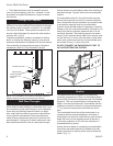
Figure 9 shows another method of passing a connector
through a wall. All combustible material in the wall is cut
away to provide the required clearance that is 3x the
connector diameter. The resulting space must remain
empty. A flush-mounted sheet metal cover may be used
on one side only. If covers must be used on both sides,
each cover must be mounted on noncombustible spac-
ers at least 25 mm (1”) clear of the wall.
DO NOT CONNECT AN ENCORE MULTI-FUEL TO
ANY AIR DISTRIBUTION SYSTEM.
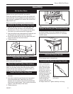
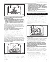
Hearths
This appliance must be installed on to hearth that
meets the requirements of Part J of the Building Regu-
lations 2000 (Combustion Appliances and Fuel Storage
Systems). This can be achieved by ensuring that the
hearth is constructed and sized in accordance with the
guidelines included in section 2 of approved document
‘J’. The size and clearances of the hearth are as fol-
lows:
The constructed hearth should be constructed in ac-
cordance with the recommendations in document J,
and should be of minimum width 840 mm and minimum
depth 840 mm (if a free standing hearth b) above) or
a minimum projection of 150 mm from the jamb (if a
recessed hearth a) above).
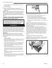
Unless the stove hearth is completely noncombustible,
the bottom heat shield should be installed to provide
radiant protection for framing which may be below the
hearth. (Fig. 11)