


8
Dutchwest Non-Catalytic Convection Heater
30003849
ST797
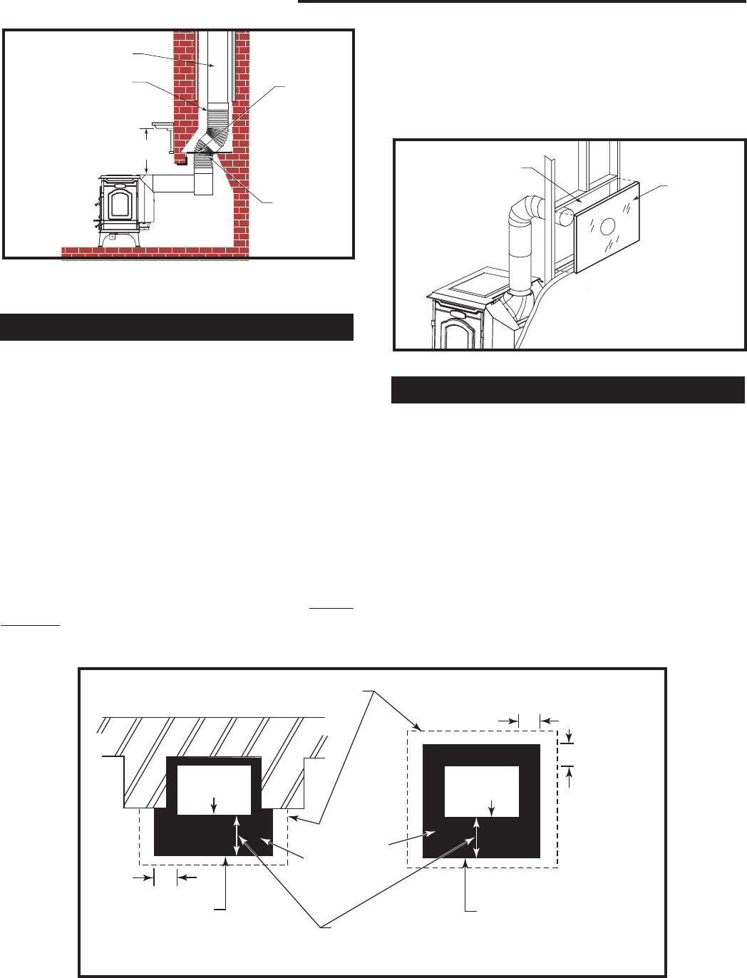
thru fireplace
5/04
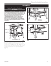
Flue Liner
Extend Chimney Con-
nector to the First Tile of
the Flue Liner
Observe
Miniumum Clearances
Damper
Plate is
Removed
or Locked
in Open
Position
Close Off
the Damper
Opening with
Sheet Metal
and Sealant
ST797
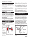
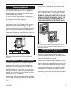
Fig. 8 The connector passes through the fireplace to enter
flue. Special Fireplace Adapter Kits to simplify fireplace instal
-
lations are available from your local dealer.
ST421
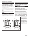
hollow wall pass through
6/2/04 djt
457 mm (18”) Empty
Space All Around the
Chimney Connector
Sheet Metal
Cover
(One side
only)
ST421
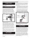
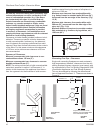
Fig. 9 Hollow wall pass-through.
Wall Pass-Throughs
Whenever possible, design your installation so the con-
nector does not pass through a combustible wall. If you
must use a wall pass-through in your installation, check
with your building inspector before you begin and con-
struct it in accordance with local building codes. Also
check with the chimney connector manufacturer for any
specific requirements.
Accessories are available for use as wall pass-
throughs. If using one of these, make sure it has been
tested and listed for use as a wall pass-through.
Figure 9 shows one method, in which all combustible
material in the wall is cut away to provide the required
457 mm (18”) clearance for the connector. The resulting
space must remain empty.
A flush-mounted sheet metal cover may be used on one
side only. If covers must be used on both sides, each
cover must be mounted on non-combustible spacers
at least 25 mm (1”) clear of the wall. Your Dutchwest
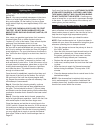
Hearths
This appliance must be installed on to hearth that
meets the requirements of Part J of the Building Regu-
lations 2000 (Combustion Appliances and Fuel Storage
Systems). This can be achieved by ensuring that the
hearth is constructed and sized in accordance with the
guidelines included in section 2 of approved document
‘J’. The size and clearances of the hearth are as fol-
lows:
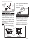
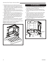
The constructed hearth should be constructed in ac-
cordance with the recommendations in document J,
and should be of minimum width 840 mm and minimum
depth 840 mm (if a free standing hearth b) above) or
a minimum projection of 150 mm from the jamb (if a
recessed hearth a) above).
Costructional Hearth
Dimensions as below
At least
300 mm
At least 150 mm
or to a suitable
heat resistant wall
At least
150 mm
Hearth Surface
Free of Com-
bustible Material
Perimeter should be
clearly marked e.g.
edge of superimposed
hearth
Perimeter should be
clearly marked e.g.
edge of superimposed
hearth
Appliance
Doors
Appliance
Doors
ST912
Fig. 10 Noncombustible hearth surface dimensions.
a) Fireplace recess b) Free standing
dealer or your local building inspector can provide de-
tails of other approved methods of passing a chimney
connector through a combustible wall.
DO NOT CONNECT THE HEATER TO ANY AIR DIS
-
TRIBUTION DUCT OR SYSTEM.