


6
Dutchwest Non-Catalytic Convection Heater
30003849
Single-Wall Connector
The single-wall chimney connector should be made of
24 gauge or heavier steel, and must have a minimum
internal diameter of 152 mm (6”) for model 2477CE.
Install single-wall chimney connector not less than 457
mm (18”) from the ceiling.
In cathedral ceiling installations, extend the prefabricat-
ed chimney downward to within 2.4 m (8’) of the stove.
The entire chimney connector should be exposed and
accessible for inspection and cleaning.
Do not use galvanized chimney connector; it cannot
withstand the high temperatures that can be reached
by smoke and exhaust gases and it may release toxic
fumes under high heat.
Double-Wall Connector
Information on assembling and installing double-wall
connectors is provided by the manufacturer of the
double-wall pipe. Follow the manufacturer’s installation
instructions exactly. Most manufacturers of prefabri-
cated double-wall insulated chimneys also offer double-
wall connector pipes. Using a chimney and connector
pipe from the same manufacturer helps simplify the
assembly and installation.
NOTE: For installations using double-wall connec-
tors, minimum clearances must conform to listed
clearances in the Stove and Chimney Connector
Clearance Charts on Page 12 and 13 of this manual.
Assembling Single-Wall
Chimney Connector
SAFETY NOTE: Always wear gloves and safety
goggles when drilling, cutting or joining sections of
chimney connector.
For double-wall
connectors, follow
the manufacturer’s
instructions exact-
ly. For single-wall
connectors, follow
the instructions
below.
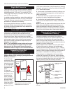
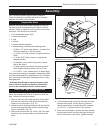
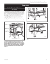
1. Insert the
crimped end of the
first section into
the stove’s flue
collar, and keep
each crimped end
pointing toward
the stove. (Fig. 4)
Using the holes in
the flue collar as
guides, drill 3 mm
(1/8”) holes in the bottom of the first section of chimney
connector and secure it to the flue collar with three #10
x 1/2” sheet metal screws.
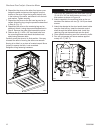
2. Secure each joint between sections of chimney con-
nector, including telescoping joints, with at least three
sheet metal screws.
3. Secure the chimney connector to the chimney. In-
structions for various installations follow below.
4
.
Confirm that the installed stove and chimney con-
nector are correct distances from nearby combustible
material.
NOTE: Special slip pipes and thimble sleeves that form
telescoping joints between sections of chimney con-
nector are available to simplify installations. They can
eliminate the need to cut individual connector sections.
Consult your local dealer about these special pieces.
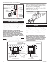
Securing the Connector to a
Prefabricated Chimney
Follow the installation instructions of the chimney
manufacturer exactly as you install the chimney. The
manufacturer of the chimney will supply the acces-
sories to support the chimney, either from the roof of
the house, at the ceiling of the room where the stove is
installed, or from an exterior wall.
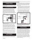
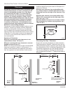
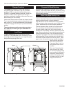
Special adaptors are available from your local dealer
to make the connection between the prefabricated
chimney and the chimney connector. (Fig. 5) The top
of such adaptors attach directly to the chimney or to the
chimney’s ceiling support package, while the bottom of
the adaptor is screwed to the chimney connector.
These adaptors are designed so the top end will fit
outside the inner wall of the chimney, and the bottom
end will fit inside the first section of chimney connector.
Any soot or creosote falling from the inner walls of the
chimney will stay inside the chimney connector.
ST419
Joining the chomney
6/27/00 djt
Prefab (Insulated)
Chimney
Ceiling Support
Package
Prefab Chimney
Adapter
Chimney Connector
(Stovepipe)
ST419
Fig. 5 Joining the chimney connector to a prefabricated
chimney.
ST242
Chimney connector
12/13/99 djt
Toward
Stove
Flue Gas
Direction
ST242
Fig. 4 Crimped sections always point
toward the stove so that any liquid
condensation will not leak out.